I think the key word here is "similar", since that's all we got to work with whether with real tubes or SPICE models. Another takeaway is that Schade and crazy drive or "enhanced triode" could do wonders for the multi-grid tubes, and both allow more tweaking opportunities than the UL or the CFB connections, not to mention cheaper OPT's.
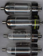
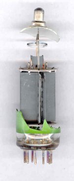
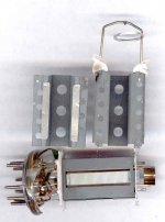
A picture of the 6CB5A tube types traced .
Top to bottom: RCA grey round, Sylvania grey round, RCA grey rectangular, "Sylvania/National" black plate
I don't have any of the old "coke bottle" types.
Top to bottom: RCA grey round, Sylvania grey round, RCA grey rectangular, "Sylvania/National" black plate
I don't have any of the old "coke bottle" types.
Attachments
Last edited:
Address messages sent. Thanks for the tube offers guys!
Three 13GB5's should be delivered tomorrow. They arrived in Hickory today. There are 2 Mullards, and one Korean attempt at copying a good tube.
I don't know if it is electrically similar, or just something that was stuffed into the glass just for a particular TV. You can tell what happened to them based on weight alone.
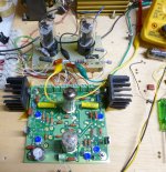
I got my breadboard back up and running. I need to test a bunch of tubes in conventional configuration for a baseline before getting "crazy" on them.
I'll keep an eye out for them. The road here just got plowed today, so the mail should be getting delivered. Warmer weather melting the snow too.
I'll have to connect the magnovals up with clip leads for now, since my pin connector lead sets fit noval or octals. Any common socket pins around that fit magnovals? (RS-232?)
I could make another set of tracer leads sometime.
I'll have to connect the magnovals up with clip leads for now, since my pin connector lead sets fit noval or octals. Any common socket pins around that fit magnovals? (RS-232?)
I could make another set of tracer leads sometime.
got about 40 of those
I have about 80 that are a variety of US brands, yet all made by Mullard. They have a dark grey metallic ring around the base, and the typical Mullard code numbers.
I have about 20 that are Korean made, ProComm brand. They have a wide green ring around the base, weigh about 1/3 as much as the Mullards, and blow up when you stuff 12 watts through them.
Any common socket pins around that fit magnovals
I don't know, I have just been forcing them into novar sockets. They only fit tight once.
They only fit tight once
same here....once fitted, you can not use the other types....
what i do with my sockets is to fit them with small pins first, if they are loose,
(yes some are) then i set them aside for use with these 13gb5 types....
all my sockets are china jobs...
OK. I baselined some tubes. All testing was with a 3300 ohm OPT.
A pair of Well toasted Chinese "6L6GC's" that have been seen on these pages with their plates glowing brightly for the past 7 years.....and I haven't blown them up yet. A pair of 6BQ6GA sweep tubes. A pair of unnamed old TV tubes that I have been meaning to test, and a pair of old radio tubes that resemble 50L6's but need 25 volts to light up. They are probably 25L6's, but have no markings.
Then I tried the 6L6GC in crazy drive....they sucked. No amount of knob turning or resistor swapping could make any power or even a relatively undistorted signal. The same tubes cranked out 75 watts at 1.8% THD on 500 volts wired as conventional pentodes.
Next I tried the 25L6's....Wired as pentodes, I decided to see how far they would go before turning into red light bulbs.......40 watts brought some pale glow in a dark room and 44 watts brought clipping. Yes, I bent the plate voltage spec a wee bit......400 volts! 120V on the screen.
Then I wired them in Crazy Drive. I took a pile of 10K 2 Watt resistors and tried different combinations to see what worked the best.....There is 5K from G2 to G1 and 20K from G1 to ground.
Does it work? The distortion at 1 watt is in the same range as it was with conventional drive, 0.15%. However clipping comes at 58 watts....along with the red glow of death! All is not perfect yet. the distortion does not rise monotonically from low power to max. It peaks at about 3.2% around 20 watts, drops back down and is still about 2.5% at 50 watts.
No more time this afternoon. Maybe later.
Attachments
Tubelab's 13GB5's arrived!
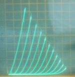
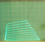
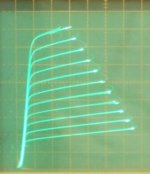
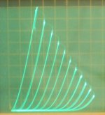
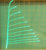
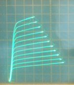
Here are curves for the 1st Zenith tube:
50 mA/div Vert., 50V/div Horiz. for all traces.
1) 13GB5 g1 pentode, 130V on g2 and -1V steps on g1 from 0V
2) 13GB5 triode mode, -7V steps on g1 from 0V
3) 13GB5 g2 drive, g2 = 110V with -7V steps down
4) 13GB5 g2 drive, g2 = 70V with -7V steps down
5) 13GB5 g2/g1 Crazy Drive, g2 = 75V with -7V steps down, Rg2g1 = 1.22K, Rg1k = 980 Ohm
Attachments


Last edited:
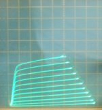
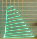
Here is another Crazy Drive curve for the same Zenith 13GB5 tube. Might be more linear than the other Crazy Drive curve, not sure. I used +6V offset on the bottom of the Rg1k resistor this time, and Rg2g1 is 2.74K (giving it a little bit more gain, hence 70V instead of 75V g2 max) (the + 6V offset helped eliminate a gain increase near zero current. I check for gain variation there by dropping the max Vg2 down and observing the curve spacing as it drops down to zero current.)
50 mA/div Vert., 50 V/div Horiz. -7V steps on g2 down from +70V
post edit:
Hmmm, I guess it looks the same. I can't seem to get the Crazy Drive to completely linearize this tube, but it is coming out better than g2 drive at least. And takes less drive swing than g2.
By the way, I use a 10 turn 20K pot for Rg2g1, and a 10 turn 2.75K pot for Rg1k for these tests (and most earlier ones).
Attachments
Last edited:
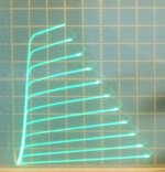
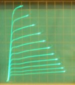
I started on the 2nd Zenith 13GB5 and found the g1 scale in pentode mode is -2V steps. (not -1V as listed above, I must have forgot I had the readout on 2V grid for the calib.) So here is the 2nd tube at 50mA/div Vert., 50V/div Horiz. in g1 pentode with -2V g1 steps from 0V and 124V on g2 (to match up with the 1st tube).
1) 2nd 13GB5 in pentode 124V on g2, -2V steps
2) 1st 13GB5 in pentode for comparison 130V on g2, should be -2V steps also
I'll get the rest of the curves for the 2nd tube shortly, just wanted to correct my mistake above.
1) 2nd 13GB5 in pentode 124V on g2, -2V steps
2) 1st 13GB5 in pentode for comparison 130V on g2, should be -2V steps also
I'll get the rest of the curves for the 2nd tube shortly, just wanted to correct my mistake above.
Attachments
Last edited:
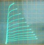
Here is the 2nd Zenith 13GB5.
(I re-did the g1 pentode curves for 130V on g2 this time.)
50 mA/div Vert., 50V/div Horiz.
1) 13GB5 g1 pentode, 130V on g2 and -2V steps on g1 from 0V
2) 13GB5 triode mode, -7V steps on g1 from 0V
3) 13GB5 g2 drive, g2 = 110V with -7V steps down
4) 13GB5 g2 drive, g2 = 70V with -7V steps down
5) 13GB5 g2/g1 Crazy Drive, g2 = 75V with -7V steps down, Rg2g1 = 1.64 K, Rg1k = 860 Ohm
-----
re-posted 1st tube (13GB5) again for comparison:
6) g1 pentode 130V on g2, -2V steps on g1
7) triode -7V steps on g1
8) g2 110V -7V steps on g2
9) g2 70V -7V steps on g2
10) g2/g1 Crazy drive g2 = 70V -7V steps
Attachments
-
 rsz_13gb5_z2_crazy_50_50_75v_7vs.jpg59.3 KB · Views: 99
 -
 rsz_13gb5_z2_g2_50_50_70v_7vs.jpg63.6 KB · Views: 90
 -
 rsz_13gb5_z2_g2_50_50_110v_7vs.jpg54.5 KB · Views: 93
 -
 rsz_13gb5_z2_triode_50_50_7vs.jpg57.3 KB · Views: 390
 -
 rsz_13gb5_z2_pent_50_50_130v_2vs.jpg64.5 KB · Views: 393
 -
 rsz_13gb5_z_crazy_50_50_70v_7vs.jpg71.9 KB · Views: 96
 -
 rsz_13gb5_z_g2_50_50_70v_7vs.jpg62.1 KB · Views: 87
 -
 rsz_13gb5_z_g2_50_50_110v_7vs.jpg59.8 KB · Views: 100
 -
 rsz_13gb5_z_triode_50_50_7.jpg63.5 KB · Views: 102
 -
 rsz_13gb5_z_pent_50_50_130v_1vs.jpg66.8 KB · Views: 96
Last edited:
WOOPS!!
Unfortunately, testing of the ProComm "13GB5" did not go well (at all).
I connected it up with the Crazy Drive still wired up from the last tube tested, and it worked well for about 1/2 a minute. (should have gotten a pic, darn) Then the plate curves started slowly shrinking down, as if the heater wires had fallen off. I checked them, and the heater was running fine. I re-configured for normal -Vg1 pentode mode, and I can only get about 150 mA max. now. It will briefly do higher current, but very rapidly shrinks back down to the 150 mA level. It does produce shrunken plate curves that almost look OK though. Mysterious. Not drawing more that 2 mA on the grid2, so likely something wrong with grid 2.
I looked through the inspection "window" in the plate with a magnifying glass, and the grid wires look fine. It never did red plate or give off a bright glow (as from a hot grid). Admittedly I was running it on the tracer with 50 Watt limiting load resistor (as done with the other 13GB5 tubes and most Sweep tubes I test). The tube spends most of its time at 1/2 that plate voltage limit, and 1/2 the max plate current when being stepped. So that should be around 12.5 Watts average I figure. The knee portion of the curves are hard on the g2 however, below Vp = 50V or so.
I guess I should have listened to George more carefully when he said these blow up at 12 Watts. They really do! George, if you still want a curve trace of these "delicate" ProComm tubes, send another one, and I will test it on the 10 Watt limit scale with low current limiting on the g2 supply. Sorry for the inconvenience.
I guess an autopsy is in order, unless someone has some suggestions for further checks on the ProComm. I tried all the redundant pins to see if a pin had internally disconnected, but no luck.
Last edited:
No problem, I wasn't even going to send it but there was room in the box. Yes, they really are POS's.
All the other 13GB5's I have are Mullard made, regardless of the brand on the box / tube. I have seen over 100 watts flow out of a pair of them for extended periods of time without issue.
I plugged a set of the ProComm tubes into the same test board, and there was a flash of light inside one of them and BOTH were dead. I was somewhere shy of 50 watts out. A second set blew up too. They remind me of the early Chinese KT88's.
I took two of the dead ones apart. One had the cathode strap blown in half, and the cathode in the other tube had chunks of the coating missing.
As the rap star said....it's hammer time! Post a picture if something unusual happened inside.
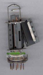
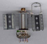
Autopsy completed. A very odd failure.
The plate halves were only attached to each other by a single weak spot weld. One plate half sprung outward some, after the hammer blow to the bottle. The grids appeared in perfect condition. The cathode was perfect too. No weak connections to the pins. But if you look closely at the last picture (center, upper plate corners, near each other), there are burn marks were the two plate halves were touching, but not welded. Even the remnant mica insulator piece attached there shows burn marking. My guess is that the two plate sections were arcing some there during operation, and maybe polluted the vacuum with metal vapor. That must have blocked cathode emission then. That would explain why (after resting a while) it would work for a short moment, then deteriorate again.
Could also be that factory activation of the getter (by induction) vaporized the plate where it was touching together. Maybe metal vapor deposited all over the place inside and on the insulators.
Attachments
Last edited:
The opinion of two people based on two smashed tubes, and the fact that these weigh about 1/3 as much as the Mullards is....that these tubes suck.
I have about 10 left around here....expect to see some glowing pictures.....if they live long enough to melt.
I have had two tubes shatter from electrical issues. One was a Russian 6P19 that I miswired causing violent decomposition on power up, and the other was an early Chinese KT88 that started sparking and arcing when operated within its ratings, so I just watched, and POP! it broke.
- Home
- Amplifiers
- Tubes / Valves
- Those Magnificent Television Tubes