I am really interested in this thread. The curves are amazing. What resistor did you almost cook? Is there a schematic of the drive you are currently testing? I am interested to see how it looks on paper.
Is there a schematic of the drive you are currently testing?
It's in post #119
What resistor did you almost cook?
The dummy load. It is rated for 125 watts, and I was feeding it 200.
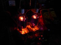
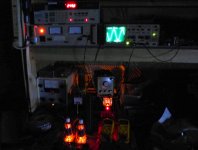
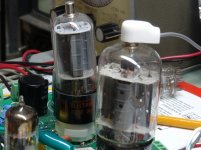
OK, 400 watt Plitron OPT installed and wired for 2500 ohms. 500 watt "George proof" dummy load installed.......CRANK. As expected clipping occurs at 250 watts. This is about the same as 35LR6 sweep tubes under the same conditions.
I let it run at 250 watts for 10 minutes, then turned out the lights and took the picture....nothing glowing. The camera "sees" infrared which shows up purple, and there is some on the heat radiator in the right hand tube, these tubes are not glowing, but close to it.
The 35LR6's had a noticeable but not bright glow under the same conditions.
The efficiency is about the same as the 35LR6's. The cathode current in each tube was 330 mA. Spec is 300. The plate voltage is 650 volts. Screen grid current is 40 ma per tube at full power. There is 377 watts going into the OPT (650* .58), and 250 watts coming out. 127 watts is being burned up in the tubes. 63.5 watts each. Spec is 50. Plate efficiency is 66%. Distortion at 250 watts was about 2%.
The distortion at low power is not as good as with the 3300 ohm OPT. It could be the harder load, or it could be current imbalance affecting the toroid OPT. They are picky about that.
Attachments

Update: Finally got one of the Cincinnati Amps built with the TV Tube Complement. 2x 6LU8 and 4x 6KD6. The OPTs are quadrifilar so one runs the screens one runs the control grids then the plate and cathode unity coupled primaries. They do 200 watts and no need to select impedances due to the current capacity of those massive cathodes. Transformers go out to over 200 kHz at half power; the only way to tame the oscillations is with plate to grid fb...
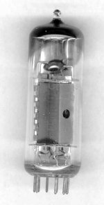
I just had a late Christmas present show up on the front steps this morning, from California! Anatoliy sent a 6pi41C, 12BQ6GTB and a 12L6GT. The 6pi41C looks somewhat similar to the 13GB5, except no plate cap. I should be able to get some curves done this weekend.
Attachments

"The question is, is 12BQ6 I sent an "old style" or a "new style"?"
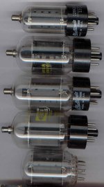
Well, it's not like any I had here. Smaller, it's most probably the 11 Watt version. See pics below.
From top to bottom:
a) the 12BQ6GTB/12CU6 you sent
b) Raytheon black plate 12BQ6GA/12CU6
c) GE 12BQ6GA/12CU6
d) Raytheon grey plate 12BQ6GA/12CU6
e) GE 12GE5 (17.5 Watt rating)
The bottom 4 all have about the same size plate. The GE one (c) looks identical inside (and tests identical) to the 12GE5 (and 12JN6, 6GY5)
Attachments
Last edited:
Well, it's not like any I had here.
I have some of those. They are 12BQ6GT or 12BQ6GTA small plate 12 watt (I think) rating.
The fat ones are 12BQ6 12BQ6GA, most have the GE "corporate" 18 watt plate. They stuck them in everything from 6BQ6's and 6AV5GA's (not GT's) to compactron sweep tubes.
Here you will see both side by side. Notice the not so straight construction of the 6BQ6GT. I called that tube the "leaning tower of power" since it was one of a pair that I extracted 120 watts from in screen drive before the big bang happened killing the tube and some other parts.
Attachments
Good thing it didn't collapse down to a black hole after supernova-ing at 120 Watts!!
George, have you ever tested a 21HB5/A to see where those red-plate? They are only rated 18 Watts, but they have a plate the size of 24 Watt tubes.
George, have you ever tested a 21HB5/A to see where those red-plate? They are only rated 18 Watts, but they have a plate the size of 24 Watt tubes.
"The question is, is 12BQ6 I sent an "old style" or a "new style"?"
Well, it's not like any I had here. Smaller, it's most probably the 11 Watt version. See pics below.
From top to bottom:
a) the 12BQ6GTB/12CU6 you sent
b) Raytheon black plate 12BQ6GA/12CU6
c) GE 12BQ6GA/12CU6
d) Raytheon grey plate 12BQ6GA/12CU6
e) GE 12GE5 (17.5 Watt rating)
The bottom 4 all have about the same size plate. The GE one (c) looks identical inside (and tests identical) to the 12GE5 (and 12JN6, 6GY5)
All of these look like 'GTBs or 'GAs. There were also other types of 6BQ6s: the first being the "Coke bottle" style. Then there were the 6BQ6GTAs. These can be recognized by their smaller cathodes. I have a couple, but they red plate badly when used in the Le Renard project I designed for the 6BQ6GA/GTB. The main difference is the slimmer bottle of the 'GTB. Both bias the same.
The Q-point for that design is 50mA/plate of bias, and that comes to 17.5W of PD. The RCA 6BQ6GTBs don't show any color at that current, nor does this seem to have had any service life consequences as the project has been running since 2007 on the same finals. Audio amplification is a good deal less demanding than "brick on the key", full power RMS mode, such as horizontal deflection duty. The hotter biasing improves both the loadline distortion estimate, and the actual sonic performance since this gets the finals into more linear territory as well as reducing x-over distortion.
The Sylvania black plate 6BQ6GTBs can take 70mA of plate current (24.5W) and not show any trace of color, whereas the RCA gray plates show just a trace of color.
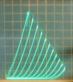
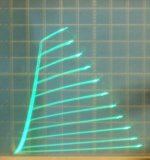
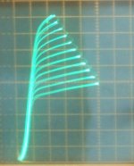
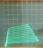
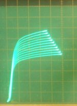
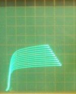
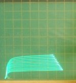
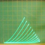
Here are some curves for the 6pi41C tube. All using 50 mA/div Vert. and 50 V/div Horiz.
1) normal g1 pentode mode, -4 V steps, 170 V on g2
2) g2 drive -7 V steps down from 100V
3) g2 drive -7V steps down from 170V
4) Crazy drive g2g1 -7 V steps down from 74 V, Rg2g1 = 780 Ohm, Rg1k = 2K
5) Triode mode -7 V steps
I had to put some ferrite cores on the clip leads for triode mode to stop it from oscillating.
----------------
I have a GU-50 that Anatoliy sent a while back. So I'll do that one next in Crazy Drive.
Attachments
Thank you Don! Looks like the best is to use 6П41С triode strapped, or pentode in push-pull. Straight screen grid drive looks usable also.
^what is the american or european analog of the 6П41С?
Supposedly very close to the 7868, with the same pin-out, but a slightly different bias point. I haven't verified any of this, so the usual caveats apply.🙂
jeff
6P13S
some says a poor man's 2A3.....25E5 are available at deeco, i have two quads of these, others are the 6CM5, EL36, i even have the japanese version...
The 6pi41C runs with lowish Vg2 like a TV sweep, while the 7868 runs with high Vg2 like an audio tube. The gm's might be similar (only data for 6pi41C I could find says gm 8400, but it doesn't specify the current for that gm, Oh it does list 56-76 mA, maybe thats it ). I think 7868 has an internal Mu of around 16.8, while the 6pi41C is around 4.7.
http://www.siberian-shop.com/6p41s-6p41c-audiophile-tetrodes-ulyanov-1970s-nos-p-611.html
6P13S and 6P44S I don't have. But some datasheets may already include a Vg2 plate curve set.
I think I did curves for 6GT5/12GT5 somewhere... Can compare those curves with whatever tube you want to cross to.
http://www.siberian-shop.com/6p41s-6p41c-audiophile-tetrodes-ulyanov-1970s-nos-p-611.html
6P13S and 6P44S I don't have. But some datasheets may already include a Vg2 plate curve set.
I think I did curves for 6GT5/12GT5 somewhere... Can compare those curves with whatever tube you want to cross to.
Last edited:
would the 6gt5's come close?
Glancing at the data sheets, I'm gonna say no, but I've been wrong before.🙂 7868 looks like a purpose built audio tube with a really high screen voltage rating compared to a typical sweep tube. Unlike smoking-amp, I have no way to run curves, sadly.
jeff
Last edited:
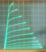
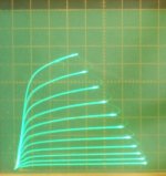
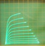
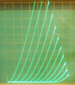
Here are some curves for the GU-50.
50mA/div Vert. (unless otherwise noted), 50 V/div Horiz.
1) normal pentode mode, 4.4V g1 steps, Vg2 = 260V, Vg3 = 0V
2) normal pentode mode, 4.4V g1 steps, Vg2 = 260V, Vg3 = +20V
3) g2 drive, 7V steps down from +260V, +15V on g3 (not much g3 effect)
4) g2 drive, 7V steps down from +200V, +15V on g3 (not much g3 effect)
5) g2 drive, 7V steps down from +130V, +15V on g3 (not much g3 effect)
6) triode mode, 7V steps, 20 mA/div Vert. 0V on g3 (tiny effect)
7) triode mode, 7V steps, 50 mA/div Vert. 0V on g3 (tiny effect)
For g2 drive, grid 2 started glowing above +200V (due to high plate currents with only a limited 70V g2 sweep and using the 50 Watt limiting load resistor on the curve tracer)
Attachments
-
 rsz_gu50_g1_44vs_260v_50_50_0vg3.jpg61.6 KB · Views: 271
 -
 rsz_gu50_g1_44vs_260v_50_50_+20vg3.jpg61.8 KB · Views: 251
 -
 rsz_gu50_g2_7vs_260v_+15v_50_50.jpg50.2 KB · Views: 252
 -
 rsz_gu50_g2_7vs_200v_+15vg3_50_50.jpg52.2 KB · Views: 251
 -
 rsz_gu50_g2_7vs_130v_+15vg3_50_50.jpg57.1 KB · Views: 259
 -
 rsz_gu50_t_7vs_20madiv.jpg66 KB · Views: 115
 -
 rsz_gu50_t_7vs_50madiv.jpg59.3 KB · Views: 114
Last edited:
- Home
- Amplifiers
- Tubes / Valves
- Those Magnificent Television Tubes