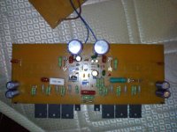
This is my Amp
I checked many times with this board... I couldnt find any any faults in placing components. But im not satisfied with the board which i created myself.
When I give +30/-30 supply it will drive woofer very slowly and can here sound inside my room. drivers are getting hot slowly (without heat sink) but not power transistors.
planning to my a new transformer to supply required voltage and check.. at this moment im broke 😀
thanks Alex and Carlos for supporting
Best regards,
Lycanlk
Attachments
disconnect the speaker.
Short the input to signal ground.
Measure the DC output at the speaker terminals.
Measure the AC output at th speaker terminals.
Short the input to signal ground.
Measure the DC output at the speaker terminals.
Measure the AC output at th speaker terminals.
Both are 0
My multimeter cannot measure millivolts but when I measure both AC and DC output by connecting input terminals (with +/- 30 supply), both values are 0.😕
My multimeter cannot measure millivolts but when I measure both AC and DC output by connecting input terminals (with +/- 30 supply), both values are 0.😕
we can exclude output offset as the problem.
Similarly LF output is also low.
we need to look at Vbe across all the output devices right back to VAS stage.
Take care, shorting any two pins of a transistor is very likely to blow up many/some of the active devices.
Similarly LF output is also low.
we need to look at Vbe across all the output devices right back to VAS stage.
Take care, shorting any two pins of a transistor is very likely to blow up many/some of the active devices.
hooooooooreeeeeeeeeeey...
Thanks for the guide Andrew.. finally I found the fault it was the output resister ..LOL
It works fine now and i cant increase the volume now caz its midnight.. I think my neighbor has a gun 😀 wish looks like this amp is a power hunger.. i feel sorry about my speakers.. we'll see tomorrow..
sound so clear but I think i need to increase the input gain from my input device .. its a chip that read USB direct and output to headphone (I dont know about output gain of the chip)
And need to boost bass. Since I dont have a pre-amp to drive this i need to increase the bass level and the input gain somehow.
currently no distortion, no hum and no noises.. overall a good amp 🙂
more comments later...
thanks everybody for the support !
Output inductor ....?
..... output inductor stil missing 😕 , must be present on output !
Regards Alex .
..... output inductor stil missing 😕 , must be present on output !
Regards Alex .
Yes Alex...
I fixed that too.. It sounds so loud now but im not satisfied with the bass level.. which i normally hear more bass 😉 i believe its because of my input signal.. anyways I can hear a clear punch.. no distortions.. I love that..
Apart from that.. one side of the amp is getting hotter than the other side.. I think its because I didnt adjust the bias.. isnt it?
It drives my woofer fully with +/-30. and I can imagine what if I give +/- 85 or more 😀 and It divers only with 3 pairs of transistors still 😎 A very good design.. highly customizable .. hehehehe..
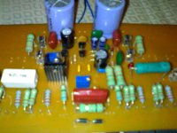
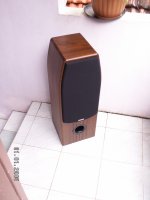
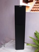
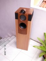
Here some pics of what we make here.. all are handcrafted products...
I fixed that too.. It sounds so loud now but im not satisfied with the bass level.. which i normally hear more bass 😉 i believe its because of my input signal.. anyways I can hear a clear punch.. no distortions.. I love that..
Apart from that.. one side of the amp is getting hotter than the other side.. I think its because I didnt adjust the bias.. isnt it?
It drives my woofer fully with +/-30. and I can imagine what if I give +/- 85 or more 😀 and It divers only with 3 pairs of transistors still 😎 A very good design.. highly customizable .. hehehehe..
Here some pics of what we make here.. all are handcrafted products...
Attachments


The best method is to adjust the bias trimpot to read 1 milivolt DC
into all emitter resistances.... read over the resistance....say..the DC milivoltimeter goes touching each resistance extreme leads, one resistance each time..be sure all them are conducting a very small current.
The current to each transistor will be the reading expressed in volts, or 0.001V divided by the resistance value...let's say you use 1 ohm.
The the result is 1 miliampere to each transistor.
This may be different from transistor to transistor..one can have more or less, and this is normal, but be sure all them will have reading, this ensure that all transistors are conducting.
Nice and by power amplifier you are building.... inform your supply voltage and current...also your speaker impedance.
regards,
Carlos
Nice pictures Lycanlk....very nice..thank you by your kindness to share with us
Thank you very much.
regards,
Carlos
Thank you very much.
regards,
Carlos
Gifts received from Dudainc, Sakis and Taj
All them forum friends.
thank you very much folks!
regards,
Carlos
YouTube - Gifts from Dudainc, Sakis and Taj
All them forum friends.
thank you very much folks!
regards,
Carlos
YouTube - Gifts from Dudainc, Sakis and Taj
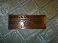
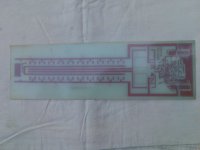
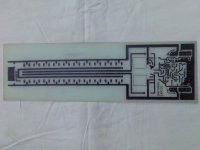
pcb pattern under development
i am very sorry to place my opinion but i think that your pcb is very poor ...
at this rail voltage and with so many transitors there is going to be way too much power and your pcb traces are too small ....
----the rail trace is very very small ( thin )
---- there is too many corners in the pcb ( it is supposed to be rounded )
---- in designs like that power is feed in the midle so power and amp drawing will equalize from side to side to the transistors
---- there is too many parallel lines in your pcb and this can cause complications and or oscilations
He cannot do much better dear Sakis.... too many transistors
You will always have the length or the width to run wires..unless you build a sandwich style..... alike a building..many stores, many stages...many floors... one transistor over the other..above the other..heatsink blades down the transistors...all then packed alike a indian toten pole..... other ways...we gonna have long parallel run of copper lines.... big distance between copper lines can be helpfull reducing capacitances from line to line..and some small capacitors (10pf) from colector to base may stop oscilations that can be generated there... the source of possible oscilations can be the combination of copper line length (inductance) with the parallel line creating capacitance...acting, behaving, alike 2 blades into a capacitor......then....installing the capacitor to "tune" that thing into frequencies higher than the maximum oscilating frequency the transistor can operate you will fix the hole thing..interesting...trying to force oscilation to avoid oscilation..this way you will force oscilations to happens ABOVE the maximum frequency the transistor can operate considering the voltage and current it will hold.
You know, alike a Radio Frequency "tank" circuit..a tuned circuit..the long copper line as inductor and the capacitor working together tuning certain frequency that is above the maximum oscilating capacity you have into your transistor..if he cannot oscilate into so high frequency, then you will be rid of oscilations...the capacitor can be 3pf, 5pf, 6.8pf, 8.2pf, 10pf...well...just tune the whole thing to oscilate into a "non possible oscilating frequency"
I hope you have received my thanks dear Sakis, about the parts you have sent...I have lost your email adress because i have re-installed my Windows XP Professional SP2...i made that downgrade because i had audio problems while using the Windows 7 and Vista..and audio is very important for us..the audio turn compressed, or limited...when i was increasing bass into the Windows Media Player equalizer (and other software used too) i was having reduction into the treble..and this happened using several amplifiers..not the amplifier fault...the software fault...i have checked replacing amplifiers by others.
I have changed the audio (on board) by an off board audio board and still had troubles....
This resulted i have losted some adresses...also my E mail "sent" messages because i have cleaned all stuff during the "format" process...i also have changed my Browser software too...i have lost your eastelectronics personal adress.
Please, write a message to me dear Sakis..this way i will have your personal adress back again.
carlos.eugenio1951@yahoo.com
I have published a video showing the parts i have received from you, from Taj and from Dudainc..i hope you have watched that one.
regards to Maria and a kiss to little Sakis (what is his name?)
Carlos
Last edited:
thank you very much uncle charly i wish all the parts will find their way in to nice powerfull amps
thanks on your comments about pcb design .....
i can be found @
east_electronics@yahoo.gr
devicemanager@eastelectronics.gr
info@eastelectronics.gr
service@eastelectronics.gr
i will be very happy to receive your voice mails and pictures again
kind regards sakis
thanks on your comments about pcb design .....
i can be found @
east_electronics@yahoo.gr
devicemanager@eastelectronics.gr
info@eastelectronics.gr
service@eastelectronics.gr
i will be very happy to receive your voice mails and pictures again
kind regards sakis
- Status
- Not open for further replies.
- Home
- Amplifiers
- Solid State
- This is the DHR.... Dx High Resolution Turbo