Non-magnetic screws
Why not use bronze screws and nuts? They are not magnetic.
They will secure the weight better and not get deformed by the heat.
What I would wonder is if transformer's vibration shouldn't be isolated somehow from the enclosure.
Carlos
Peter Daniel said:So, maybe it would be a good idea to use plastic or fiberglass screws to mount transformer?
Why not use bronze screws and nuts? They are not magnetic.
They will secure the weight better and not get deformed by the heat.
What I would wonder is if transformer's vibration shouldn't be isolated somehow from the enclosure.
Carlos
what is moamps's suggestion? To use the C2 C3 and C5 caps? I use themPhilo said:Bricolo,
I think the noise rejection in those meters would prevent you from seeing the oscillation. Have you tried our suggestions? Particularly moamps' and gpapag's? I think that is where your solution lies.
King 30,
I put the 1uF mylars across +/- DC outputs of the bridges and immediately notice a smoother delivery. Peter is using BG 4,7uF across his discrete rectifiers.
Peter, could you post a pic of your rectifier build? Did you make a PCB for them like your Alephs?
I'll try qpapag's suggestion to place 220uF caps on the supply rails, on the chip
For qpapag: I was told to wire +In with it's own wire to the star ground, and then in+mute and stdby-gnd together to ground. OK so far
But where do I connect my PSU bypass caps? One side to +PWVs, and the other side to ground, but wich pin? +in, or mute and stdby?
I think I'll leave the 0.1uF caps where they are (they are soldered directly to Vs (+ and -) and I'll add the 200uF ones directly on the PWVs pins) but as sayd before, I don't know where to get the mass for those
carlmart said:Why not use bronze screws and nuts? They are not magnetic.
They will secure the weight better and not get deformed by the heat.
What I would wonder is if transformer's vibration shouldn't be isolated somehow from the enclosure.
Carlos
Peter,
I have seen toroids held down with cable ties, and I have seen them broken due to heat and/or transporting.
Carlos suggests mechanical isolation mounting, and me too - I suggest a spring sort of like below is likely advantageous.
Eric.
Attachments
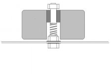
Vertical Isolation.
The dark grey part is epoxy or suitable filler with sliding fit hole (tubeing).
Spring could be engine valve spring.
Transformer is intended to sit on top of a spring.
Eric.
The dark grey part is epoxy or suitable filler with sliding fit hole (tubeing).
Spring could be engine valve spring.
Transformer is intended to sit on top of a spring.
Eric.
I don't clearly understant the concept
the transformer will not touch the case's bottom
A screw will be fiwed at it's bottom to the case, and at it's top to the transformer, but with a dampening material
am I right?
the transformer will not touch the case's bottom
A screw will be fiwed at it's bottom to the case, and at it's top to the transformer, but with a dampening material
am I right?
Bricolo said:I don't clearly understant the concept
the transformer will not touch the case's bottom
A screw will be fiwed at it's bottom to the case, and at it's top to the transformer, but with a dampening material
am I right?
The dark grey is solid epoxy or whatever material that glues and fills the middle of the transformer to say, half way down, and has a tubular hole through the centre.
A bolt and locknut are fixed to the bottom of the case.
A spring is fitted over the vertically mounted bolt, and the transformer/epoxy centre assembly is fitted over the vertical bolt and slid down to engage the spring.
A nylock nut is fitted to the top of the vertical bolt to retain the transformer, but has clearance.
This enables the transformer to 'float' on the spring, provided that the vertical friction is minimal, and that the spring is soft enough to isolate the transformer and cabinet from each other.
Brass bolt and nuts might be best.
Eric.
If there is enough room, it would be interesting to add another spring on top, for more secure mounting.
This enables the transformer to 'float' on the spring, provided that the vertical friction is minimal, and that the spring is soft enough to isolate the transformer and cabinet from each other.
BUT if the vibrational energy from the transformer doesn't go into the casing, where does it go? It can't disappear according to science. Will it instead add some sort of frequency 'boost' to the power line? (I don't know this, I'm only suggesting it)
I always remove transformers from the case containing the circuits/CD drive etc. If I still wanted to negate their vibrations, I would build a box with a false bottom and add dry sand to the lower compartment. That way the vibrations agitate the sand particles which rub against each other and transform the energy into heat.
An alterantive if you want to keep transformer/power supply and circuits in the same case would be to create a base plate beneath the base of the casing and bolt the transformer to that, at the same time isolating it from the case (in a similar arrangement to the one suggested. The casing would then be isolated from the new baseplate by whatever means are preferred.
Hi!
I just began to reassemble my GC (but I use LM3876 instead of 3875), using the actual simplified schematic aka P. Daniel (adapted to LM3876, of course), and since I do not use an input pot, I had to put a resistor from input to ground, in order to get rid of hum.
I started with 50 k, but together with the resistor in series to input (10k), the GC played way too quiet. So now I'm reducing the resistor to ground step by step, but I am wondering if there maybe is a formula to do this?
I made this assumption: When I use a pot (say, 50k), and turn the volume up to its full extend, there is nearly no reistance at all from input to ground, so nearly the whole signal goes to the OP. In order to simulate this with a fixed resistor, isn't maybe a value as close to zero as possible ther right way to do it?
But maybe I'm on the wrong track...?
Bye,
Arndt
Actually, the pot always has 50K to ground but the output(in to amp) is variable. Your input goes to the high side of the "winding", ground goes to low side and your out to the amp goes to the center "wiper" connection. As you turn your volume up you reduce the resistance between the input and the output to the amp.
And also by turning the pot all way up you increase the input to ground resistance which is max 50K and that's when the amp plays the loudest. If you decrease resistance to ground you will also decrease the signal to the amp.
It is the series resistance which is decreasing for the amp to be louder and at pot at max volume it is zero.
It is the series resistance which is decreasing for the amp to be louder and at pot at max volume it is zero.
Ok, I understand that, but I simply cannot get the GC to play loud enough, if I connect the input to ground, using whatever value for resistor - I went as low as 10 ohms, and it was louder, but still not anywhere near as loud as without any connection to ground.
And: The smaller the value of the resistor to ground, the hotter the IC gets. In fact, so much more hotter than without any connection to ground at all, while that produced the best output level (but with a slight hum while no music was playing)...
And tried the series / to ground setup of R. Elliot right now, but without changing the feedback resistor the amp produced some nice bird-like noises... guess 220k is too much for that setup...
Still, I want this thing to work until I go out this evening... so back to soldering iron...
Bye,
Arndt
And: The smaller the value of the resistor to ground, the hotter the IC gets. In fact, so much more hotter than without any connection to ground at all, while that produced the best output level (but with a slight hum while no music was playing)...
And tried the series / to ground setup of R. Elliot right now, but without changing the feedback resistor
the amp produced some nice bird-like noises... guess 220k is too much for that setup...Still, I want this thing to work until I go out this evening... so back to soldering iron...
Bye,
Arndt
Hi!
If I understand you right, I should decrease the value of the resistor in series to input, while leaving the resistor to ground at 50k?
Btw. thanks for quick help...!
Arndt
Peter Daniel said:And also by turning the pot all way up you increase the input to ground resistance which is max 50K and that's when the amp plays the loudest. If you decrease resistance to ground you will also decrease the signal to the amp.
It is the series resistance which is decreasing for the amp to be louder and at pot at max volume it is zero.
If I understand you right, I should decrease the value of the resistor in series to input, while leaving the resistor to ground at 50k?
Btw. thanks for quick help...!
Arndt
That's what I meant. If your amp gets hot without playing really loud, it might be oscillating.
Hi!
Well, it doesn't get really hot...
It simply was colder when I had no connection from input to ground at all... I would actually be quite happy with that setup if it wasn't for the hum (which isn't really audible once the music is playing).
Peter Daniel said:That's what I meant. If your amp gets hot without playing really loud, it might be oscillating.
Well, it doesn't get really hot...
It simply was colder when I had no connection from input to ground at all... I would actually be quite happy with that setup if it wasn't for the hum (which isn't really audible once the music is playing).
Well, I use those well-know conrad aluminium chassis (actually, one chassis for two ICs...), but right now the chassis is not connected to ground (I plan to do so with a 0.47 uF capacitor in series).
The hum is only there when I connect the cinch cable, so maybe the impedances of my soundcard and the GC don't match...
But the hum totally disappears with the signal-ground connection, while that leads to the amp playing quieter...
Right now I exchanged the 10k resistor (series to signal) for 1k, still too quiet (with 50k to ground)...
I must've killed some quadrillion brain cells up to now by inhalating those soldering fumes...
I am not sure what sound card you are using but I have my Audigy card hooked into one of my GC inputs and I have no problems. I just matched the output of the sound card to my CDP and tuner. Could be like Peter says and you have some interference. I have a tiny wobble on my oscope at 0 volume, (no input) and the amp only get slightly warm after an hour or so of playing. Not even as warm as my tuner or CDP.
Hi!
I have an Audigy as well (but of course powered with kxProject drivers...).
What do you mean by matching the output - connecting?
Or actually measuring the impedance? Or do you mean matching the volume?
I think that my main probs originate from not using a pot, but I still don't want to do so (my whole setup actually worked very well with my old Marantz STK amp, from which I blew one channel last week, see another thread... and that amp, like my End Millenium, had no pot, either...
There must be a way to do this... 😕 decreasing the series resistor did only help a little bit. I went down to 220 ohms, and still not somewhere near the output level if leaving out the resistor from input to ground...
Think I will not finish tonight 😡
Got some partying to do...
Arndt
Philo said:I am not sure what sound card you are using but I have my Audigy card hooked into one of my GC inputs and I have no problems. I just matched the output of the sound card to my CDP and tuner. Could be like Peter says and you have some interference. I have a tiny wobble on my oscope at 0 volume, (no input) and the amp only get slightly warm after an hour or so of playing. Not even as warm as my tuner or CDP.
I have an Audigy as well (but of course powered with kxProject drivers...).
What do you mean by matching the output - connecting?
Or actually measuring the impedance? Or do you mean matching the volume?
I think that my main probs originate from not using a pot, but I still don't want to do so (my whole setup actually worked very well with my old Marantz STK amp, from which I blew one channel last week, see another thread... and that amp, like my End Millenium, had no pot, either...
There must be a way to do this... 😕 decreasing the series resistor did only help a little bit. I went down to 220 ohms, and still not somewhere near the output level if leaving out the resistor from input to ground...
Think I will not finish tonight 😡
Got some partying to do...
Arndt
- Status
- Not open for further replies.
- Home
- Amplifiers
- Chip Amps
- This is not just another gainclone