gpapag said:
Bricolo
You don't have to be confused. Just return everything to star ground with it's own wire. To make it easier:
1.Pin 1
2.Input's plug ground
3. Pin 3
4. Pin 4.
5. Each by-pass capacitor
6. Speakers (-)
7. PSU's ground.
(1-4 can be done with thin wire, like AWG 28)
Try to place Star ground not far away from the chip. Sometimes i find it beneficial (less hum) to connect 2 & 3 not directly to star ground, but through a 10 Ohm resistor (suggested by Mr. Cherry). The metal chassis is mandatory to be connected to safety earth. Whether you will connect safety earth with star ground, is something you have to deside by experimentation. You may use a switch ("ground lift" in audio jargon), for to see which case gives the less hum.
Good luck
Regards
George
I think I'll have to make an analog ground for each channel, or I'll spend all my money in cable 😀
I think I'll have to make an analog ground for each channel, or I'll spend all my money in cable
Bricolo, if you are using a separate power supply, you make all your connections to star ground in the amplifier (as GPAPAG told you) and then run a single wire back from the star ground to the star ground in the power supply box.
As regards the cables from the power supply to the amp, bigger isn't necessarily better!
Nuuk said:
BUT if the vibrational energy from the transformer doesn't go into the casing, where does it go? It can't disappear according to science. Will it instead add some sort of frequency 'boost' to the power line? (I don't know this, I'm only suggesting it)
Very good question

Nuuk said:
Bricolo, if you are using a separate power supply, you make all your connections to star ground in the amplifier (as GPAPAG told you) and then run a single wire back from the star ground to the star ground in the power supply box.
As regards the cables from the power supply to the amp, bigger isn't necessarily better!
My transformer is in the same box, and I use 2 diode bridges for the whole amp (one for +, the other for -)
Is this a good ides to make 2 star grounds, one near each chip, and connect them to the main ground with a wire?
I know thicker isn't necessary better, but for the output and the power rails, I find the cable a bit too thin, don't you think?
Arndt,
Ok, I am duplicating your setup in my prototype with some sample LM3876s I have, but need to know what you used on the mute leg so I can use it as well. According to tha datasheet, if you don't meet the criteria for that leg you'll have attenuation problems. Don't give up!
Peter, thanks for the pics and schematic! I am orering some today plus I might take out the linefilter in my amp. Just to see. 😉
Bricolo said:
My transformer is in the same box, and I use 2 diode bridges for the whole amp (one for +, the other for -)
Is this a good ides to make 2 star grounds, one near each chip, and connect them to the main ground with a wire?
I know thicker isn't necessary better, but for the output and the power rails, I find the cable a bit too thin, don't you think?
Try using the rectifiers isolated if your transformer can support it. One for each channel. I would stick to one ground for now. One trick I picked up in here was using CAT5e for DC supply cable. Use the striped for neg and the solid for the pos. Works great.
Philo said:
Try using the rectifiers isolated if your transformer can support it. One for each channel. I would stick to one ground for now. One trick I picked up in here was using CAT5e for DC supply cable. Use the striped for neg and the solid for the pos. Works great.
what do you mean in using the rectifiers isolated?
I mean don't cross connect the two. Try using one to supply both the pos and neg for one channel. Take a look at my pics a couple of pages earlier.
Hi!
Thanks for reply.
I seem to have isolated the problem, but I don't know why it behaves that way.
I know that this is not the best way to do it, but always thought that at least I could do it that way: I use a 25 - 0 - 25 toroid, with a single rectifier (build with BYW 29/200 diodes), and a single 3-lead (could be made 4) to the amp. At the amp power connector I connect V+ and V- for both ICs to the same point, and the connection for ground is my grounding star point.
Now it seems that both channels work absolutely OK if I just connect one of them to the supply, good sounds, hooray. But when both are connected, the music comes out distorted and the ICs have a heating problem. But I know that this should work, as for example R. Elliots PCB for the LM3876 works the same way (but with much more components, of course, which could make the difference).
The rest of my setup (I'm doing this at work, but should be right):
47k metal from input to ground (simple resi, had nothing else right now)
10k metal RC55 Welwyn from signal to inverting input (9)
221k metal RC55 Welwyn as feedback (between pin 3 and 9)
22k metal RC55 Welwyn from muting to V- (8 to 4) <- MUTING
22 uF Panasonic FC from muting to ground (8 to 7) <- MUTING
1200 uF Panasonic FC from V+ to ground (1 to 7)
1200 uF Panasonic FC from V- to ground (4 to 7)
power connected with four leads: V+ to 1, V- to 4, Ground to 7, Ground to 10 (the non-inverting input)
Speaker connected to pin 3
Bridge setup:
Four BYW 29/200 Diodes, with 2 * 220uF Panasonic FC on rails
The only thing I can think of to test this evening is putting a zobel in, or substituting the connection to ground from pin 10 (the non-inverting input) with an impedance / bypass, like in the first THOR GC. But don't know if that would help.
Cannot be that I am awaiting the parts for building P3A and cannot even get this to work correctly...!
Thanks,
Arndt
Philo said:Arndt,
Ok, I am duplicating your setup in my prototype with some sample LM3876s I have, but need to know what you used on the mute leg so I can use it as well. According to tha datasheet, if you don't meet the criteria for that leg you'll have attenuation problems. Don't give up!
Peter, thanks for the pics and schematic! I am orering some today plus I might take out the linefilter in my amp. Just to see. 😉
Thanks for reply.
I seem to have isolated the problem, but I don't know why it behaves that way.
I know that this is not the best way to do it, but always thought that at least I could do it that way: I use a 25 - 0 - 25 toroid, with a single rectifier (build with BYW 29/200 diodes), and a single 3-lead (could be made 4) to the amp. At the amp power connector I connect V+ and V- for both ICs to the same point, and the connection for ground is my grounding star point.
Now it seems that both channels work absolutely OK if I just connect one of them to the supply, good sounds, hooray. But when both are connected, the music comes out distorted and the ICs have a heating problem. But I know that this should work, as for example R. Elliots PCB for the LM3876 works the same way (but with much more components, of course, which could make the difference).
The rest of my setup (I'm doing this at work, but should be right):
47k metal from input to ground (simple resi, had nothing else right now)
10k metal RC55 Welwyn from signal to inverting input (9)
221k metal RC55 Welwyn as feedback (between pin 3 and 9)
22k metal RC55 Welwyn from muting to V- (8 to 4) <- MUTING
22 uF Panasonic FC from muting to ground (8 to 7) <- MUTING
1200 uF Panasonic FC from V+ to ground (1 to 7)
1200 uF Panasonic FC from V- to ground (4 to 7)
power connected with four leads: V+ to 1, V- to 4, Ground to 7, Ground to 10 (the non-inverting input)
Speaker connected to pin 3
Bridge setup:
Four BYW 29/200 Diodes, with 2 * 220uF Panasonic FC on rails
The only thing I can think of to test this evening is putting a zobel in, or substituting the connection to ground from pin 10 (the non-inverting input) with an impedance / bypass, like in the first THOR GC. But don't know if that would help.
Cannot be that I am awaiting the parts for building P3A and cannot even get this to work correctly...!
Thanks,
Arndt
Progress report:
I just added a 220k resistor bypassed with 0.1 uF from non-inverting input to ground (before it was just a simple connection to ground), and voila: the distortions are gone!
But now I have the hum back !!!!!
!!!!!
Like I said before: This is driving me nuts!
OK, maybe I would consider using separate bridges / cables for each channel, but this would mean bying (and working on) another casing, bying new connectors etc. etc., so I really want to do it this way!
One thing I will try out now, is substituting all cables inside the GC with solid metal pins (actually office paper clips 😉 ), maybe this will help...
I just added a 220k resistor bypassed with 0.1 uF from non-inverting input to ground (before it was just a simple connection to ground), and voila: the distortions are gone!
But now I have the hum back
!!!!!Like I said before: This is driving me nuts!
OK, maybe I would consider using separate bridges / cables for each channel, but this would mean bying (and working on) another casing, bying new connectors etc. etc., so I really want to do it this way!
One thing I will try out now, is substituting all cables inside the GC with solid metal pins (actually office paper clips 😉 ), maybe this will help...
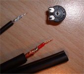
Is this a problem if I use shielded cable (see the picture in one of my previous posts) even for the grounded pins?gpapag said:
Bricolo
You don't have to be confused. Just return everything to star ground with it's own wire. To make it easier:
1.Pin 1
2.Input's plug ground
3. Pin 3
4. Pin 4.
5. Each by-pass capacitor
6. Speakers (-)
7. PSU's ground.
(1-4 can be done with thin wire, like AWG 28)
Try to place Star ground not far away from the chip. Sometimes i find it beneficial (less hum) to connect 2 & 3 not directly to star ground, but through a 10 Ohm resistor (suggested by Mr. Cherry). The metal chassis is mandatory to be connected to safety earth. Whether you will connect safety earth with star ground, is something you have to deside by experimentation. You may use a switch ("ground lift" in audio jargon), for to see which case gives the less hum.
Good luck
Regards
George
I only have those 2 (the big one and the little one, I plan to use the big for output and +/- rails)
Is this a problem if I use shielded cable (see the picture in one of my previous posts) even for the grounded pins?
I only have those 2 (the big one and the little one, I plan to use the big for output and +/- rails)
Bricolo
You may have problems routing this thicker cable. But technically speaking, No there is no problem in using this cable.
Regards
George
OK, when I'll finished (after I'll started it 😀) the case fot this amp, I'll use the shielded cable
the thin one seems to be 23AWG, the big one 20AWG
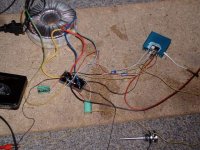
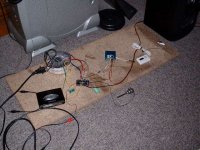
for the momment, I'm using such poor cable, and everything is on the floor in such a mess. I'd be banned from this forum if I post a photo of my setup 😀
but it works (except heat problem that seems to be oscillation)
the thin one seems to be 23AWG, the big one 20AWG
for the momment, I'm using such poor cable, and everything is on the floor in such a mess. I'd be banned from this forum if I post a photo of my setup 😀
but it works
(except heat problem that seems to be oscillation)Bricolo said:for the momment, I'm using such poor cable, and everything is on the floor in such a mess. I'd be banned from this forum if I post a photo of my setup 😀
What do you mean? Show us the chaos... not everyone is Peter Potter 🙂
dave
planet10 said:
What do you mean? Show us the chaos... not everyone is Peter Potter 🙂
dave
Attachments
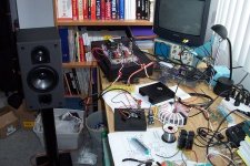
Hard-core wired...
With this layout...i'm not surprised! 😉
Salut!
it works (except heat problem that seems to be oscillation)
With this layout...i'm not surprised! 😉
Salut!
- Status
- Not open for further replies.
- Home
- Amplifiers
- Chip Amps
- This is not just another gainclone