The POT has a bigger diameter than the knob, no way i can feed a line trough! And as you can see a couple of posts back, there is not that much room inside the GC aswell.
Basically you need one wire to the LED, the knob shaft and chassis acts as ground. So if one pin of the LED touches the knob, you need one wire to supply the power. If you bore the back of the knob, it will provide space for the wire to fold. Make a hole in front panel for the wire to go out and attach to the LED. It's a simple solution but it should work. Make sure that the wire is flexible enough.
Peter Daniel said:Basically you need one wire to the LED, the knob shaft and chassis acts as ground. So if one pin of the LED touches the knob, you need one wire to supply the power. If you bore the back of the knob, it will provide space for the wire to fold. Make a hole in front panel for the wire to go out and attach to the LED. It's a simple solution but it should work. Make sure that the wire is flexible enough.
Sorry, but the shaft is plastic, however we could use the nut from the POT to act as ground. I think i'll try it tomorrow, but first i have to find the LED's we want to use.
Jerry T.,
If I had known the led in knob would be such a hot spot, I would have shown my theory a while back. I have no value to the EE types around here, but I am decent in a shop. . .
I suggest, assuming you have access to machine shop tools, to turn out a knob and drill a 1/4" hole 9/10 the way through where you want the led. Pierce the other side with a 1/32" drill to make the view hole. Relieve the knob in a torroid fashion 3/4 of the diameter of the knob. Specifically, if it is a 1" knob, turn a 3/4" dia slot about 1/8" deep by 1/8" wide on the backside of the knob around the diameter. Glue the LED in with a 2-part epoxy after soldering 18-20ga stranded wire to it, 2 or 3" longer than the LED. Wrap the wire 1 and 1/2 turns around inside the torroid in the back of the knob and through an 1/8" dia hole in the panel. The 1.5 turns will act as a spring when the knob turns. Keeping slack in the arrangement, install the knob and solder the leads to the power LED leads on your board. Now, when you rotate the knob through the 270 deg of the pot rotation, the wire will expand in the slot as required and still power your LED.
If you and Maarten are not fit with a lathe, this is not that easy. However, if you have the tools, this is quite easy and should allow you to power the LED.
My claim to fame in the knob fabrication department was to be turning an Absolute Vodka cap into a volume knob on a Gainclone. Guess I've donated that tidbit now, but putting an LED in a knob could be easy with that plan as well.
Good luck and put it to work. You have a great looking piece now, so put that last bit of effort into making it historical.
Sandy.
Sandy H. said:Glue the LED in with a 2-part epoxy after soldering 18-20ga stranded wire to it, 2 or 3" longer than the LED. Wrap the wire 1 and 1/2 turns around inside the torroid in the back of the knob and through an 1/8" dia hole in the panel. The 1.5 turns will act as a spring when the knob turns.
Nice, Sandy H, very nice indeed!
Jerry T: Even without big machine tools, access to a Dremel or other small electric rotary tool will allow you to carve slots and other grooves. Just clamp the knobs in your vice well. If you have them, use the wood or aluminum jaw liners and if you have the vee-shaped pipe holders, even better. The results won't be perfect, but if they are hidden away, then it won't matter.
There are other more creative ways to use power tools, but I won't recommend them, even though I've been foolish enough to try them.
🙂ensen.
PS: Please use safety goggles.

Sandy H. said:Jerry T.,
If I had known the led in knob would be such a hot spot, I would have shown my theory a while back. I have no value to the EE types around here, but I am decent in a shop. . .
I suggest, assuming you have access to machine shop tools
Sandy.
purplepeople said:
Nice, Sandy H, very nice indeed!
Jerry T: Even without big machine tools, access to a Dremel or other small electric rotary tool will allow you to carve slots and other grooves.
🙂ensen.
PS: Please use safety goggles.
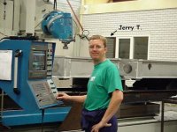
I've got a complete C.N.C. factory at my disposal, so tools aren't the problem. The problem is getting things to work propperly after they are machined. Here's a pic of me at work. (don't laugh)
Attachments
Re: Knobjob
You could try to drill a hole in your pot's axis and put an isolated wire through it
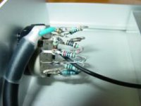
Jerry T. said:Thanks for all the info guys, this is what i've done.
All i have to look into now, is how to get the wires trough the chassis. But that shouldn't be a problem now!
PS. sorry for the poor quality photo's, but you'll get the idea.
You could try to drill a hole in your pot's axis and put an isolated wire through it
Power Supply
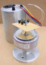
Here is an update of the Power Supply section. Now that I'm mounting the small board with the rectifier I'm wondering how these were mounted in the original Power Humpty.
I'll use only half of the board as the tube is large enough to accomodate two transformers. This way i'll leave room for two separate power supplies in one tube. Anyway I was just wondering whether there are smarter ways to get the rectifier section in the tube apart from the way shown on the photo...
Pictures floating around on the internet of the "original" gaincard (if of the original) give a messy impression, but maye the Power Supply was of higher quality. Anyone pictures of the inside of a Power Supply of $3000?
Maarten
PS. The sound of the prototype is very nice 😎 (running on the power supply of my other clone)
PS2. Rest of story on http://gainclone.platenspeler.com
Attachments
Looks like Jery wins The "Best Shop" award!
That box is looking good- I even liked the original knobs. Throw around a few recessed bolt heads and it would have loooked good! But now that you are going for the LED I don't want to distract you from that!
Most people here seem to be in the '60s Danish Modern design warp- mainly cause they want their gear to look like "real " high end audio stuff. If you actually look at "real " high end stuff you will see some pretty "out there" designs!
So when are you gonna program that big boy to spit us all out
machined boxes with webs and machined nooks and crannies and cooling slots woooie!? A pretty bad business idea -trust me . Few of us are probably willing to spend for even the raw aluminum block, but it is hard not to fantasize about an over machined cool box.
Re: Re: Knob LED
If you can extend the switch with a 6 mm. alu tube you can do it easily. See my post in
this thread for pics and explanation.
/U.
Jerry T. said:It is mounted on a 6mm diameter axle. I was thinkin' about, drilling a hole trough the switch's axle (length) and put the wires trough to feed the LED. But i don't know if that is possible.
If you can extend the switch with a 6 mm. alu tube you can do it easily. See my post in
this thread for pics and explanation.
/U.
Re: Re: Re: Knob LED
Unfortunately there is no room for extension with an aluminum tube. In the prototype there is nearly enough room for the attenuator, the resistors are already bending backwards more than I like. The idea is nice though, maybe we can drill a hole through the switch.
Maarten
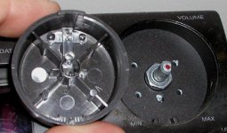
Ps. A photo of the switch we use for volume control ...
Nisbeth said:
If you can extend the switch with a 6 mm. alu tube you can do it easily. See my post in
this thread for pics and explanation.
/U.
Unfortunately there is no room for extension with an aluminum tube. In the prototype there is nearly enough room for the attenuator, the resistors are already bending backwards more than I like. The idea is nice though, maybe we can drill a hole through the switch.
Maarten
Ps. A photo of the switch we use for volume control ...
Attachments
Maarten,
In your power supply configuration, will not the threaded rod through the transformer and the aluminum case create a shorted turn?
SRMC
In your power supply configuration, will not the threaded rod through the transformer and the aluminum case create a shorted turn?
SRMC
Good point! They even warn for this in the manual of the toroids. You can destroy the toroids by allowing current to pass through the bolt!!!
Fedde
Fedde
I don't see any difference between mounting the toroid the conventional way, or like we have done? 
Instead of the normal bolt we have used a longer one, for the rest we use the same parts that come with the toroid.
But if there are any problems i can make nylon covers for the toroid.
Instead of the normal bolt we have used a longer one, for the rest we use the same parts that come with the toroid.
But if there are any problems i can make nylon covers for the toroid.
SRMC said:Maarten,
In your power supply configuration, will not the threaded rod through the transformer and the aluminum case create a shorted turn?
SRMC
I am fairly sure that because of the way torroids transformer works, it is not a concern to use metal rods going through its center.
BTW: very nice work Jerry&Maarten!
I am jealous 🙂
(do you happen to be located near the east of NL !?)
Regarding the inside: I would strongly advise to consider two extra BG N's as friends for your coupling caps. BG's anti-parallel sound IMHO much better (better known as position 69 🙂). More smooth&liquid. Worth the extra few euros. (BG's are not so expensive anymore these days !!!)
Keep us updated about your listening results and maybe comparisons with other gear!
Fedde
Jerry T. said:I don't see any difference between mounting the toroid the conventional way, or like we have done?
Instead of the normal bolt we have used a longer one, for the rest we use the same parts that come with the toroid.
But if there are any problems i can make nylon covers for the toroid.
That will not help. The point is that current will flow through the bolt! The current can go through the bolt and return via the case. The primary side will induce currents and it will be a short. The only way to avoid this is to isolate one side of the bolt. I don't know what happens if you isolate the two sides of the bolt and mount two toroids on it. I think that will work...
Fedde
- Status
- Not open for further replies.
- Home
- Amplifiers
- Chip Amps
- This is not just another gainclone