We are playing at very high frequencies which could make things sensitive. This isn't a spherical source, but the conical shaped diaphragm looks even worse. Also the length of the line may not be at the right scale to see the solution clearly.
What is the cause of the nulls?
What is the cause of the nulls?
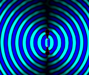
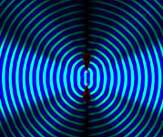
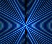
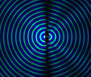
It looks to be behaving more like a driver in a flat baffle although no nulls directly on axis
Attachments

Last edited:
So, if it's possible Scott, could you repeat the procedure as per post #36 (or #39) but add a gap approximated to an 8" driver in between and include that triangular 'extras'?
Like this? It's behaving similar to a flat baffle again
Attachments
Hmm. Can we deduce from this that at higher frequencies where the driver operates as a point source, there are fewer 'nulls' but as the driver produces longer waveforms, the 'nulls' reappear?
The modelling appears to be consistent and the next question would be how closely does it represent an actual physical driver and how do we go about evaluating this?
Does the same pattern change significantly if the angle of the triangles is doubled to 60 degrees? Also, can you can alter those 'gap triangles' to have curved sides like a parabolic function, and if so, would this change the overall pattern of nulls (assuming such a thing is possible)?
I've often wondered if a waveguide on a FR driver baffle would reduce the uneven radiating pattern like the spherical chamber does and here we are, actually modelling a similar thing, and including the rear surface too!
Thanks for trying these things for me too - both of you - it's really interesting.
… bedtime now.
^"30 degrees is enough".
"the worst baffle is a baffle oriented towards the listening position"
move off the axis
We are playing at very high frequencies which could make things sensitive.
When I suggested a donut/toru, my idea was for a LF dipole source, not a HF waveguide. The sims that you are showing seem to be at a very HF - short wavelengths. I would not think that such a design would work well above the point where the wavelength/2 is about the size of the source.
That certainly seems effective above the dipole peak https://www.diyaudio.com/forums/multi-way/361169-polar-response-frame-ob-speakers-6.html#post6370340 The wave guide appears to help eliminate nulls higher up and makes the off axis null consistent. Of course the tool doesn't take into account the driver.
Yes, I was thinking it would be better to come back to the frequency where a plain dipole sees its first HOM, and work up slowly in frequency.I would not think that such a design would work well above the point where the wavelength/2 is about the size of the source.
It began because the sim has no frequency scale.
Not sure whether OS can bring out a very long straight source to spherical? (Though it's probably moot with trying to use drivers this way into breakup). I feel if so it would take a device impractically larger than the current toys. Better cross that bridge when we get to it.
Attachments
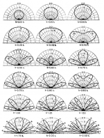
The sim doesn't know anything about drivers. The waveguide eliminates the largest on axis null which is the first one above the dipole peak. A flat baffle with round over doesn't have the same effect, see attachment. The sim isn't clear on the first null, tricky to get frequency low enough to show it properly.Hmm. Can we deduce from this that at higher frequencies where the driver operates as a point source, there are fewer 'nulls' but as the driver produces longer waveforms, the 'nulls' reappear?
It becomes more horn like if the angle is increased, not something we want I don't think? I've tried parabola, no real differenceDoes the same pattern change significantly if the angle of the triangles is doubled to 60 degrees? Also, can you can alter those 'gap triangles' to have curved sides like a parabolic function, and if so, would this change the overall pattern of nulls (assuming such a thing is possible)?
Attachments
Last edited:
Hmm, maybe it's time to mockup a version and see what happens - would a sealed reasonably smooth styrene surface be okay with an 18mm centre for driver mounting ?
I think the sim has too many limitations to be certain and that it needs to be done with better software.
Try a search for model liferings 🙂Hmm, maybe it's time to mockup a version and see what happens - would a sealed reasonably smooth styrene surface be okay with an 18mm centre for driver mounting ?
Good idea, thanks - another 'outside the box' thinking - love it! (I wouldn't have thought about that).
I was cogitating about the possible difference between the front and rear radiating pattern but getting a bit ahead of myself.
Interestingly, I don't think the 'null' points at the rear are especially significant IF you use diffusers or distance from wall behind is above that critical 5 feet (I'm playing with Tim Perry's 'leanfusers' at the moment) but could be wrong about this.
They're a bit far away from you, but this sort of thing 🙂 Life Rings - decorative life rings, model life rings with mirror, decorative life buoys for sale in the UK, life rings with clocks for the beach decoration themed home, seaside bathroom, garden or boat or as a marine gift. Decorative life buoys and l Real ones are an option but possibly too large
I think an issue with nulls at the rear is that they have the effect of reducing the null off axis.
I think an issue with nulls at the rear is that they have the effect of reducing the null off axis.
Last edited:
Hmm, I wonder if we have something like this over here …
One idle thought seeing that one with rope on the perimeter is to make a whole new one using coiled up thick rope and covering it with material - it might have to wait until we're released from confinement/lockdown/etc that we're all getting fedup about and our media is doing very selective reporting ...
It looks like you are heading down the same path and guys like that Malthouse aren't helping
This doesn't seem to be representative as I can't get it to produce a null directly on axis.Do you want a finite source .txt?
Not sure whether OS can bring out a very long straight source to spherical?
An OS is for a circular source. A Prolate Spheroidal coordinate system allows for a long thin line to be made spherical. This is covered in my book. There is also the elliptic cylinder as a close approximation.
Hmm, maybe it's time to mockup a version and see what happens -
Are you able to take measurements?
- Home
- Loudspeakers
- Multi-Way
- This is either very wrong or I have still not understood diffraction from baffle edge