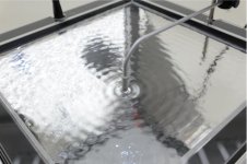
I've been using this Ripple Tank Simulation to simulate a dipole doughnut............Can someone explain what these green pattern are supposed to represent?

In the context of the thread this "worry" is very relevant, you might be surprised.Where did all the worry about cabinet diffraction get started?
Granted, speakers today are all designed to eliminate cabinet issues due to that "effect".
Odd, that some of the best, most popular and sonically pleasing speakers were not designed with that worry in mind.
AR's, KLH's, Advents, etc....
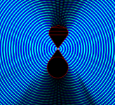
One thing, and I feel stupid asking this but is this donut profile with the central filled triangle areas what's bneing called the "OS"?
Okay, that out of the way …
Thanks Scott, I get the idea from your #36 post that the round donut profile of the second photo (simulated behavior) will produce some of the expected rear radiating uneven distribution null/pressure areas
The first photo is showing a far better front and rear radiating pattern and I gather is an application of Allen's post #31 - the question I have is 'how do you achieve this central loading "focusing triangles" is practice'?
Could the donuts be fabricated to include these 'filled-in' areas but allow cut-out "scallops" or a mounting plate where the driver is to be mounted? Some idle speculation but trying to stay 'outside the square' (as the saying goes!)
Now, from your photo post #39, it seems that having edges at 30* (top profile shape)is enough and the curved surface (bottom profile) isn't necessary - this would make fabrication much simpler.
I know this is just a conceptual theory but is there any idea about the physical sizes of the diagrams and particularly for low frequency limitations?
This is quite interesting ...
I played around with some numbers and started from some of the previous posta about using a baffle size about 500mm square to get a 150Hz rolloff - the Caintuck Audio tombstone shaped baffle with the 8" FR Betsy is about this size - I could be quite optimistic too ..
Anyway, starting with this size, this would equate to the front half of the donut also having a surface distance of 500mm, yes? So the round toroid wall diameter would need to be about 330mm, yes? And if an 8" driver was used, this would make the donut about 860mm wide, about 32" (2.6 ft)
Could someone 'critique' my assumptions, please? This seems rather large for a midrange baffle.
Perhaps not, I'm getting some on axis nulls, also the off axis null is wider and more consistent with the waveguide.Flat baffle seems to sim just as well, the important thing is the edges.
While we're assuming, the high frequency extension takes out one of the baffle size constraints. No longer do you need to make it smaller to reach higher. Size would seem to be constrained by efficiency.Could someone 'critique' my assumptions, please?
Now, from your photo post #39, it seems that having edges at 30* (top profile shape)is enough and the curved surface (bottom profile) isn't necessary - this would make fabrication much simpler.
Why not make it a square doughnut so long as the edges are sufficiently "rounded"?
Okay, now we have to see if the torus shape can work the same with the driver space in between the two halves as per Allen concept drawing in post #31
So, if it's possible Scott, could you repeat the procedure as per post #36 (or #39) but add a gap approximated to an 8" driver in between and include that triangular 'extras'?
So, if it's possible Scott, could you repeat the procedure as per post #36 (or #39) but add a gap approximated to an 8" driver in between and include that triangular 'extras'?
Really you want the point source to be the size of the driver, I don't know how to do that, Allen might, I've only been playing with this since yesterday.
Sorry, I missed your last post - yes, that could work okay, I think
A torus/donut with a square cross section, inner diameter of 8" (plus a central mounting flange) and just taper the inner 'donut' square surfaces at 30 degrees, both front and back.
Hmmm, could be done fairly easily with styrene and a hot-knife …
A torus/donut with a square cross section, inner diameter of 8" (plus a central mounting flange) and just taper the inner 'donut' square surfaces at 30 degrees, both front and back.
Hmmm, could be done fairly easily with styrene and a hot-knife …
Sure. Create two line sources. Put them back to back, they may need to be separated by a wall. Right click on one and change phase.
No, I meant a square baffle, does it really need to be circular since we seem to have mitigated the edge diffraction?
Yes, save them as txt?Also, you can save these so you don't need to keep redrawing them.

- Home
- Loudspeakers
- Multi-Way
- This is either very wrong or I have still not understood diffraction from baffle edge