Thank you for this simple yet elegant and simple design. I have incorporated this into a DAC and have tested it for a few months with excellent results. I have a few boards left if anyone is interested.
DAC Main Board Photo by Pandaemonium19 | Photobucket
DAC Main Board Photo by Pandaemonium19 | Photobucket
DAC Back Photo by Pandaemonium19 | Photobucket
DAC Main Board Photo by Pandaemonium19 | Photobucket
DAC Main Board Photo by Pandaemonium19 | Photobucket
DAC Back Photo by Pandaemonium19 | Photobucket
Question. Now that both the lme49610 and lme49990 are both EOL, what does this mean for those of us that want to build this? I know that theres a group buy for the 49610, but sadly does not cover the 49990.
waveforms show ClassB surge and non-harmonic ringing
Summary, for now: I view the VDD network to also be a design issue.
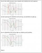
Here is an example of VDD ringing with 4" wire (100 nanoHenries) and 1,000 uF VDD capacitor with ESR of 0.001 ohm (1 milliohm) ringing at 16KHz.
Note the non-harmonic relationship between the ClassB current surge and the spacings of zerocrossing of the ringing.
Summary, for now: I view the VDD network to also be a design issue.
Here is an example of VDD ringing with 4" wire (100 nanoHenries) and 1,000 uF VDD capacitor with ESR of 0.001 ohm (1 milliohm) ringing at 16KHz.
Note the non-harmonic relationship between the ClassB current surge and the spacings of zerocrossing of the ringing.
Attachments
PI networks in VDD path need predictable dampening
Summary, for now: I view the VDD network to also be a design issue.
Here are two VDD networks with PI networks: 1milliFarad at the VDD supply, 1uH of wiring (~1 meter), and 100uF located by the OpAmp.
In both cases, the 1mF has 3milliOhm ESR and 100uF has 1milliOhm ESR.
The ringing frequency is set by the smaller of the caps, and the total loop inductance, producing approx 16KHz Fring.
In the 2nd case, an additional cap with high losses is placed in parallel, at the OpAmp, with the 100UF. This new cap has 1nH ESL and 1nH PCB trace inductance. Note the 16KHz ringing is not affected.
What is going on? These lovely low-ESR high-value capacitors will produce audible ringing, if not dampened.
Use the formula R_zeta1 = 2*sqrt(L/C) to compute the critical-dampen R value.
Attachments
If I could upvote this post - I would. Very-very often people forget (or don't even think) about this and put a bunch of high Q caps in parallel without any damping.
Absence of damping in signal chains could be frightening either.
And it is not as random here as it may look 🙂
Absence of damping in signal chains could be frightening either.
And it is not as random here as it may look 🙂
Summary, for now: I view the VDD network to also be a design issue.
Here are two VDD networks with PI networks: 1milliFarad at the VDD supply, 1uH of wiring (~1 meter), and 100uF located by the OpAmp.
In both cases, the 1mF has 3milliOhm ESR and 100uF has 1milliOhm ESR.
The ringing frequency is set by the smaller of the caps, and the total loop inductance, producing approx 16KHz Fring.
In the 2nd case, an additional cap with high losses is placed in parallel, at the OpAmp, with the 100UF. This new cap has 1nH ESL and 1nH PCB trace inductance. Note the 16KHz ringing is not affected.
What is going on? These lovely low-ESR high-value capacitors will produce audible ringing, if not dampened.
Use the formula R_zeta1 = 2*sqrt(L/C) to compute the critical-dampen R value.
I'm still confused. About what schematic are you talking?
3 examples of how Capacitor ESR controls VDD peaking
Here are more details on VDD as design issue.
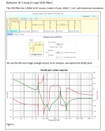
The circuit has 2 adjacent and interacting PI CLC filters, with 1mF, 100UF, 1UF. Baseline ESR is 1milliOhm in all 3 capacitors. I've set the ESLs to values I consider likely for small and large capacitors.
You'll notice how increasing the ESR has excellent reduction/dampening effect on peaks.
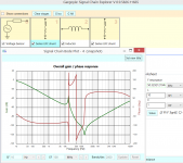
Figure A provides the schematic and baseline frequency/phase response.
Figure B provides details of all the caps and non-parasitic inductors.
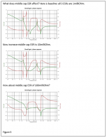
Figure C has 3 freq curves, for 1milliOhm, 10milliOhm, 100milliOhm ESR in the 1mF cap.
Figure D has freq curves for 1uF cap.
Figure E has freq curves for 100uF cap.
Here are more details on VDD as design issue.
The circuit has 2 adjacent and interacting PI CLC filters, with 1mF, 100UF, 1UF. Baseline ESR is 1milliOhm in all 3 capacitors. I've set the ESLs to values I consider likely for small and large capacitors.
You'll notice how increasing the ESR has excellent reduction/dampening effect on peaks.
Figure A provides the schematic and baseline frequency/phase response.
Figure B provides details of all the caps and non-parasitic inductors.
Figure C has 3 freq curves, for 1milliOhm, 10milliOhm, 100milliOhm ESR in the 1mF cap.
Figure D has freq curves for 1uF cap.
Figure E has freq curves for 100uF cap.
Attachments
Summary, for now: I view the VDD network to also be a design issue.
Here are two VDD networks with PI networks: 1milliFarad at the VDD supply, 1uH of wiring (~1 meter), and 100uF located by the OpAmp.
In both cases, the 1mF has 3milliOhm ESR and 100uF has 1milliOhm ESR.
The ringing frequency is set by the smaller of the caps, and the total loop inductance, producing approx 16KHz Fring.
In the 2nd case, an additional cap with high losses is placed in parallel, at the OpAmp, with the 100UF. This new cap has 1nH ESL and 1nH PCB trace inductance. Note the 16KHz ringing is not affected.
What is going on? These lovely low-ESR high-value capacitors will produce audible ringing, if not dampened.
Use the formula R_zeta1 = 2*sqrt(L/C) to compute the critical-dampen R value.
Is the resistance in a copper wire doing anything here, or am I missing something? If the one meter distance is covered with #20 AWG wire then 2 meters of that wire will have 67milli-Ohms of resistance, happens to be the exact critical damping resistance, in another words, you don't need to damp it with extra resistance.
Last edited:
natwa/tankcircuitnoise
"Is the resistance in a copper wire doing anything here, or am I missing something? If the one meter distance is covered with #20 AWG wire then 2 meters of that wire will have 67milli-Ohms of resistance, happens to be the exact critical damping resistance, in another words, you don't need to damp it with extra resistance."
Correct. Except copper has a high temperature coefficient: 0.4% per degreeC. Thus at cold temperatures, say 0degC, you have 8% less resistance and thus some ringing (if zeta > 1, or Q > 0.5).
This gives credibility to the adage: let the equipment warm up.
I view the value of appropriate dampening to be greater than needed.
Copper foil squares of standard 1 ounce/foot 1.4mil thick (35micron)
have almost exactly 0.0005 ohm (1/2,000th ohm) resistance. Using GND planes and VDD planes may not provide enough Rdampening.
Again............VDD has to be designed, and you've just shown the design is partly a *mechanical* design task.
thanks for the comment
tank
Predicting 66dB Signal/Coloration Ratio from VDDringing (PSRR on)
tankcircuitnoise: Summary, for now: I view the VDD network to also be a design issue. Here is: 1uH, 100uF, 20milliOhm R_dampen
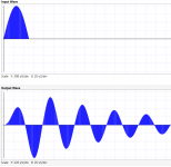
Here is Part2 of a simulation (Part1 simply computes Load Current flowing through ESR of VDD filter, as a ClassB pullup current from OpAmp)
predicting 66dB ratio between desired Signal into headphone at 10Khz, and the undesired 16KHz ringing/coloration.
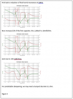
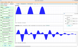
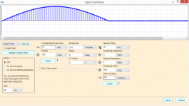
First figure shows two waveforms: (1) the distorted ClassB OpAmp pullup current, from 200 milliWatt headphone signal (5.3 volts PP) at current of 166mA; we use 3 pulses of ClassB to show how LC stored energy may fight the incoming energy; (2) the buildup of LC energy over 3 ClassB pulses, followed by the Q=5 (20milliOhm ESR) dampened response.
We use a utility to compute the #bits and multiply that by 6dB/bit.
With 5.3 volts PP at 10Khz, and a mere 2.34milliVolts at 16Khz, we see 11 bits or 66dB signal/coloration.
Second figure shows the macromodel producing the 16KHz ringing.
Upper left corner is the schematic; VDD components are in red.
Third figure shows the ClassB stimulus: frequency, voltage (computed as 0.166 amps * 0.020 Ohms), and #timesamples for the signal.
tankcircuitnoise: Summary, for now: I view the VDD network to also be a design issue. Here is: 1uH, 100uF, 20milliOhm R_dampen
Here is Part2 of a simulation (Part1 simply computes Load Current flowing through ESR of VDD filter, as a ClassB pullup current from OpAmp)
predicting 66dB ratio between desired Signal into headphone at 10Khz, and the undesired 16KHz ringing/coloration.
First figure shows two waveforms: (1) the distorted ClassB OpAmp pullup current, from 200 milliWatt headphone signal (5.3 volts PP) at current of 166mA; we use 3 pulses of ClassB to show how LC stored energy may fight the incoming energy; (2) the buildup of LC energy over 3 ClassB pulses, followed by the Q=5 (20milliOhm ESR) dampened response.
We use a utility to compute the #bits and multiply that by 6dB/bit.
With 5.3 volts PP at 10Khz, and a mere 2.34milliVolts at 16Khz, we see 11 bits or 66dB signal/coloration.
Second figure shows the macromodel producing the 16KHz ringing.
Upper left corner is the schematic; VDD components are in red.
Third figure shows the ClassB stimulus: frequency, voltage (computed as 0.166 amps * 0.020 Ohms), and #timesamples for the signal.
Attachments

So, just putting a resistor (of about .2 or .3 ohms) at the output of the PSU would be sufficient? It would be nice if OPC could weigh in on this.
LME49600
I see that mouser still carries the LME49600. I looked at the data and it seems very similar. Can this be used in place of the LME49610?
Question. Now that both the lme49610 and lme49990 are both EOL, what does this mean for those of us that want to build this? I know that theres a group buy for the 49610, but sadly does not cover the 49990.
I see that mouser still carries the LME49600. I looked at the data and it seems very similar. Can this be used in place of the LME49610?
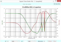
Dampening of 1,10,100milliOhm ESR with 1000,100,1,0.1uF caps
<So, just putting a resistor (of about .2 or .3 ohms) at the output of the PSU would be sufficient? >
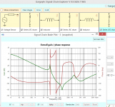
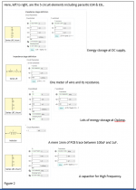
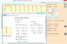
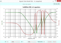
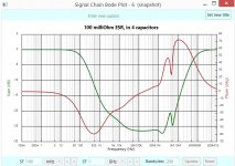
Here are 4 capacitors in parallel: 1000, 100, 1, 0.1uF with 10nH ESL for each; I show the schematic, and then sims of BODE with ESR of 1,10,100 milliohm. The VDD source resistance (on far left) is 1 ohm.
Note the smaller capacitors need higher R_dampen.
This is consistent with
R_dampen_Zetaof1 = 2 * sqrt(L/C)
<So, just putting a resistor (of about .2 or .3 ohms) at the output of the PSU would be sufficient? >
Here are 4 capacitors in parallel: 1000, 100, 1, 0.1uF with 10nH ESL for each; I show the schematic, and then sims of BODE with ESR of 1,10,100 milliohm. The VDD source resistance (on far left) is 1 ohm.
Note the smaller capacitors need higher R_dampen.
This is consistent with
R_dampen_Zetaof1 = 2 * sqrt(L/C)
Attachments
Can someone kindly explain to me how to setup the (8) LT3042 psu to be in a bipolar output?
It says it can be configured this way?
I have four of them and need to set them up to power my dual Soekris dam1021. I want to be sure I get them built properly.
It says it can be configured this way?
I have four of them and need to set them up to power my dual Soekris dam1021. I want to be sure I get them built properly.
Can someone kindly explain to me how to setup the (8) LT3042 psu to be in a bipolar output?
It says it can be configured this way?
I have four of them and need to set them up to power my dual Soekris dam1021. I want to be sure I get them built properly.
If you post this in "Power Supplies" you will probably get more help.
//
um, so I haven't touched any of this stuff for years now. I'm just getting back into things and have some questions.
I'd be interested to hear what the differences are too! I've just tried to read through this entire thread, and it looks like the original design for The Wire variants used a LME49600, but currently they use the LME49610. From what I understand the LME49610 supports a higher operating voltage (useful for some headphones), and has higher bandwidth (which isn't needed?). Are there any other differences between the two?
Also, is the LME49870 related to the LME49990 in a similar way?
I see that mouser still carries the LME49600. I looked at the data and it seems very similar. Can this be used in place of the LME49610?
I'd be interested to hear what the differences are too! I've just tried to read through this entire thread, and it looks like the original design for The Wire variants used a LME49600, but currently they use the LME49610. From what I understand the LME49610 supports a higher operating voltage (useful for some headphones), and has higher bandwidth (which isn't needed?). Are there any other differences between the two?
Also, is the LME49870 related to the LME49990 in a similar way?
From what I understand the LME49610 supports a higher operating voltage (useful for some headphones), and has higher bandwidth (which isn't needed?). Are there any other differences between the two?
That perfectly captures the differences between the two parts. I have used them interchangeably for years, and I can confirm that there is absolutely no difference in actual performance between the 600 and 610. The only reason to use the 610 is if you're running (and require) voltage rails higher than +/-18V.
For my higher power amplifiers (MPUHP and HPUHP) this is required for obvious reasons of increasing output power into loudspeakers. For headphones (and this applies to all headphones) there is absolutely no reason to run rails higher than +/-18V making the 600 and 610 both equivalent for all the headphone amps. If you really feel you need more output voltage, then go with the BAL-BAL and double the output swing to an ear-melting (and headphone melting) 23VRMS.
Also, is the LME49870 related to the LME49990 in a similar way?
I don't believe so. I think they are two fundamentally different op-amps with different performance and different voltage capabilities.
Regards,
Owen
Are there any other differences between the two?
The LME49600 also eats a lot less quiescent (idle) current than the LME49610, but that won't matter if you are running off AC and are well heat-sinked. Without the BW pin connected 7mA vs. 13mA, with BW connected 13mA vs. 19mA.
- Home
- Amplifiers
- Headphone Systems
- "The Wire" Ultra-High Performance Headphone Amplifier - PCB's