Thanks guys! Am going to put my name down for some boards. 🙂
Is there a recommended BW setting for the amps? I'll probably just assemble a SE-SE as per the schematic but if it helps....
Is there a recommended BW setting for the amps? I'll probably just assemble a SE-SE as per the schematic but if it helps....
Does anyone have any lme49610ts spares that I could snag from you? I need 6. I'm having trouble finding some. I got some from eBay and think they are fake, yet the price was not cheap either 🙁
Hope to find someone with some genuine spares that they are willing to let go. Thank you all!
Hope to find someone with some genuine spares that they are willing to let go. Thank you all!
So I'm planning to build a SE-SE into a desktop headphone amp unit. The plan is ODAC (rev B) -> SE-SE -> headphones. I'll create a new thread to ask for feedback on the design once I firm it up more, but right now:
1) If we're running the SE-SE at 1x gain, and the input is 2 Vrms, then could we get away with a +/- 6V DC supply in theory?
2 Vrms would be 2.8 V DC, and the LME chips need another 3V of headroom between the output voltage and supply rails, which is where I get that 6 V from. Realistically of course we'd want extra headroom which would accommodate 2x or 3x gain, so that pushes the minimum up to a +/- 12V DC supply which would be about a 10 V output transformer.
2) How much distance should we put between a toroidal transformer and anything in the signal path?
With the case I'm looking at and a 10 VA unit from AnTek, I'd get about 60 mm (~2.4") distance between the transformer and the ODAC. Less if I want to run a line out or aux in from the back panel. Are there shielding options I can consider? (Or maybe I should ask this in the power supply forum....)
Also, a 10 VA using is 2.4" in diameter. A 15 VA unit is 3.0". That would be even less clearance...
If an output stage can approach the supply rails, then the maximum from ±6Vdc is roughly 4Vac (12V/3)
If you know that the output stage cannot work rail to rail, then subtract that from your supply rail and then divide by 3.
eg. if the stage needs 1.2V drop, then you end up with ±4.8Vdc. rail to rail is 9.6V and max output is roughly 3.2Vac.
If there is no feedback, then the upper half of that range will suffer increasing distortion.
If there is global feedback, then in that upper output range the feedback works harder to reduce the distortion. When it finally runs out of muscle you get a hard clip. Whereas the no NFB just goes into a very soft clip.
To avoid both, I have seen suggestions to limit your max output to roughly half the maximum output.
In that last example that would allow ~1.6Vac, instead of 3.2Vac
So I'm planning to build a SE-SE into a desktop headphone amp unit. The plan is ODAC (rev B) -> SE-SE -> headphones.
.......
2) How much distance should we put between a toroidal transformer and anything in the signal path?
===========================================
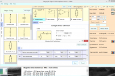
Let's consider just a long straight wire, carrying the current surges occurring at peak of the incoming 60Hz (120Hz full wave) energy. Those surges, occurring as rectifier diodes turn on, are 1 Million amp/second transients. Let's model that --- 1 Million amp/second risetime --- as coupling between a long straight wire radiating 2 inches to a similar length signal path between DAC and some OpAmp, the signal path placed 1/16" (or 1.5milliMeter) above the GND plane [loop area 2" by 1/16"].
How big a problem? Its a 1milliVolt rms 120Hz, against 5vPeak music output, problem. SNR is 70db. Its an evil buzz (I recall from teenage amplifiers).
Attachments
Last edited:
Can't find the LME49990 anymore. Any replacement possible?
Newark will have more in 9 days:
LME49990MA/NOPB - TEXAS INSTRUMENTS - Operational Amplifier, Single, 110 MHz, 1 Amplifier, 22 V/µs, 5V to 18V, SOIC, 8 Pins | Newark element14
Clicking the "check stock and lead times" link comes up with:
"358 Further stock expected to ship on Jun 29, 2016. More stock available week commencing 7/11/16"
The LME49600 are in stock again at Newark & Mouser too if anyone building OPC's Wire needs them:
http://www.newark.com/texas-instrum...ower-amplifier-class-ab/dp/84M8021?CMP=AFC-OP
http://www.mouser.com/ProductDetail/Texas-Instruments/LME49600TS-NOPB/?qs=%2fha2pyFaduhoYvnM8UFYT6zY6ZNckO%2fjm19gPTijVRnv2E3wt6tWFCny5MDNINkQ&utm_medium=aggregator&utm_source=octopart&utm_campaign=octopart-temporary-tag
Last edited:
Completed my wire se se build at long last - making for a very happy father's day indeed! Thanks so much for this wonderful little amp OPC!
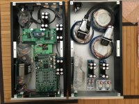
After a lot of reading up on wiring/grounding options, I opted to go with a true star ground and am pleased to report she runs dead silent, without the need for a ground breaker circuit between safety earth and star. Sound quality is fabulous, as expected, particularly when hooked up to my Yggy as a source. Will need more listening time, but I think I may prefer the wire to my mainline with th-x00's! Looking forward to trying it with my hd800's when I get around to making a xlr4 to trs adapter.
Here's a shot of the internals. Trafo is the ever popular amveco, and the build is stock but for the resistor changes (shorting r13 and 17 and 1m for r14 and 18) to allow for a 100k pot. If anyone uses this photo as a reference, please note the pot is inadvertently wired in backwards, which I promptly corrected after a very loud initial listening test. Note to self to meter this on the next build.
Link to full sized image.
After a lot of reading up on wiring/grounding options, I opted to go with a true star ground and am pleased to report she runs dead silent, without the need for a ground breaker circuit between safety earth and star. Sound quality is fabulous, as expected, particularly when hooked up to my Yggy as a source. Will need more listening time, but I think I may prefer the wire to my mainline with th-x00's! Looking forward to trying it with my hd800's when I get around to making a xlr4 to trs adapter.
Here's a shot of the internals. Trafo is the ever popular amveco, and the build is stock but for the resistor changes (shorting r13 and 17 and 1m for r14 and 18) to allow for a 100k pot. If anyone uses this photo as a reference, please note the pot is inadvertently wired in backwards, which I promptly corrected after a very loud initial listening test. Note to self to meter this on the next build.
An externally hosted image should be here but it was not working when we last tested it.
Link to full sized image.
Last edited:
An externally hosted image should be here but it was not working when we last tested it.
Link to full sized image.
Nice build! Where did you get the case from?
Nice build! Where did you get the case from?
Thanks Lucien! This is the ebay chassis I used. It is spacious relative to the boards and makes for an easy build, but I have still got to figure out some way to remove the "breeze audio" branding from the front panel. Maybe start with acetone? Also, the description references a power switch "with lamp," but FYI, the switch that the seller shipped with mine does not light up.
Thanks. I've been looking at something similar on eBay too. Size is a bit different, but it's similar enough that I guess it all comes from the same factory.
I was worried I wouldn't have enough space between the toroid and everything else which would cause interference, but your build gives me confidence. 🙂
I was worried I wouldn't have enough space between the toroid and everything else which would cause interference, but your build gives me confidence. 🙂
but I have still got to figure out some way to remove the "breeze audio" branding from the front panel.
Not sure if it helps you but I managed to remove Breeze Audio screen-printed ink from a brushed-aluminium front panel by using car brake fluid (DOT 4) and a piece of course wire scourer rubbed very lightly over the ink.
http://g02.a.alicdn.com/kf/HTB10a28LVXXXXa3aXXXq6xXFXXXj/In-case-TDA7498E-160W-160W-4ohm-2-ways-input-choose-remote-LCD-display-amplifier-DC16-32V.jpg
In my case the aluminium underneath had also been engraved with the text so it hasn't completely gone, but can't be seen from a distance now that the paint has been removed.
I couldn't get acetone or white spirit to remove the ink. From past experience brake fluid is good at removing paint.
You could maybe try this on the inside of the front panel to see if the fluid affects the black coating before attacking the front face.
Chris
Last edited:
@Lucien I was a little worried about noise as well after some earlier reports in the thread, but I think with braided or shielded inputs, star grounding and reasonable spacing between the signal/amp side and psu side, you will be all good. You'll have to share a pic of your build once up and running. Did you go with this enclosure?
@howarthcd Thanks so much for the comments and suggestions on removing the breeze branding! Good to know it is doable, provided the black faceplate can handle the same treatment as the clearcoat. I wonder why the overseas factory spent the money to mark up a diy enclosure in the first place. It is nice that they offer the precut enclosures, including iec inlets and power switches, but I can't imagine anyone actually wants the branding on their project. Seems like there would be a nice business opportunity for FPE, hammond, par metal etc to start offering a small line of precut boxes akin to the ebay stuff but made local and without any silly labeling in ugly fonts. Based on many threads here and elsewhere, it seems that there is a large number of diyaudio enthusiasts who enjoy sourcing, soldering, hookup etc. but lack access to the tools required for real chassis work. I don't know about you, but the thought of using a nibbler and file to try to cut an iec inlet, for example, sounds like less fun than a trip to have my teeth drilled.
@howarthcd Thanks so much for the comments and suggestions on removing the breeze branding! Good to know it is doable, provided the black faceplate can handle the same treatment as the clearcoat. I wonder why the overseas factory spent the money to mark up a diy enclosure in the first place. It is nice that they offer the precut enclosures, including iec inlets and power switches, but I can't imagine anyone actually wants the branding on their project. Seems like there would be a nice business opportunity for FPE, hammond, par metal etc to start offering a small line of precut boxes akin to the ebay stuff but made local and without any silly labeling in ugly fonts. Based on many threads here and elsewhere, it seems that there is a large number of diyaudio enthusiasts who enjoy sourcing, soldering, hookup etc. but lack access to the tools required for real chassis work. I don't know about you, but the thought of using a nibbler and file to try to cut an iec inlet, for example, sounds like less fun than a trip to have my teeth drilled.
Last edited:
@Lucien I was a little worried about noise as well after some earlier reports in the thread, but I think with braided or shielded inputs, star grounding and reasonable spacing between the signal/amp side and psu side, you will be all good. You'll have to share a pic of your build once up and running. Did you go with this enclosure?
Not that one, but almost the same. Black, and slightly shorter, but otherwise identical.
Hopefully I'll be able to put it together soon. (For certain definitions of "soon".) I'm actually looking at throwing together my own PCB for a SE-SE. It's simple enough for me to do a layout and get a board made (though not as cheap and quick as getting one from opc), but I'm hung up on the decoupling caps. There's a ton of opinions on the subject, and I'm not sure what to go with. I'm currently thinking 1.0 uF MLCC in parallel with 10 or 100 uF Al electrolytic per op amp per rail. Rather different from what opc has.
QUOTE=Lucien
............................
but I'm hung up on the decoupling caps. There's a ton of opinions on the subject, and I'm not sure what to go with. I'm currently thinking 1.0 uF MLCC in parallel with 10 or 100 uF Al electrolytic per op amp per rail. Rather different from what opc has.
=============================
One trick to dampen, while still providing strong surge current capability, is to add a RC in parallel with the smaller capacitors. Or simply add a low-quality capacitor (high ESR, thus lossy) in parallel with the expensive low-loss caps. Just an idea.
Challenge with adding an overt RC in parallel is the achieving the 20mOhm to 200mOhm R value. From R_damp_zeta1 = 2 * sqrt(L/C)
tank
Ah you mean like:
(0.1 µF ceramic) in parallel with (4.7 - 10 µF very low ESR cap in series with 200 mOhm resistor)
I was posting something similar in the Solid State forum. But working with higher resistance values. I was actually thinking of using a 2.2 Ohm resistor. (I really should have added a quick circuit sketch, would make it easier.)
I'm also looking at some Panasonic Al electrolytic caps. 10 µF, and either 0.7 or ~1 Ohm depending on specific model.
Ah you mean like:
(0.1 µF ceramic) in parallel with (4.7 - 10 µF very low ESR cap in series with 200 mOhm resistor)
============================================
Whereever you use a small cap in parallel with larger caps, place a similar small cap (same value, same size, same inductance) with some dampening (internal or external).
I suggest something like this:
1) 1,000UF
2) 10UF
3) 10UF with losses (internal or external)
4) 1UF MLCC expensive
5) 1UF same size, same inductance, but cheap and lossy (0.1 ohm).
Again, R_damp_zeta1 = 2 * sqrt(L/C).
I hope this is not increasing the witchcraft of power_supply design.
That SCE tool is what we used.
tank
While i'm completely new to this DIY stuff. I'm trying to implement both the BAL BAL and the SE SE in my TWO chassis build. here is a link to some of my questions about implementation of power. I have 3 trafo's and really unsure the best way to power the other chassis components. i'm open to suggestions! sounds like some of you guys REALLY know what you are doing compared to me.
http://www.diyaudio.com/forums/powe...ire-implementation-questions.html#post4765128
here is a quick preview of my state of the project right now.
I'm really unsure of the best way to implement a starground, what type of cable is best to run between chassis for secondaries. :/ Any help would be great. I would love for these amps to sound their best. I've even considered building some aluminum walls around both the PSU's, BALBAL and SESE effectively shielding them from the surrounding trafos.
Yes, my build is kinda overkill and likely subject to a lot of judgement. But it's my first project and likely i'm going to make several mistakes in this build. I would love to have the opinions of some knowledgeable people willing to guide me through some of these steps to completion.
I don't fully understand when I see builds that have grounding that has caps in the star grounding point etc. I only grasp that it's effectively dealing with keeping noise down?
yes, laugh at me if you must, but this is really my first ever attempt at building anything. I've so far completed all the soldering of the psus, amplifier boards and the normunds input/mute boards. That all went quite smoothly, and never expected the PSU's to be so tricky, but went well after using a hot air station, hotplate, solder paste and template I made.
Attachments
- Home
- Amplifiers
- Headphone Systems
- "The Wire" Ultra-High Performance Headphone Amplifier - PCB's