The last link was to a wiki.Done!
I'm not following you... you want me to attach them all somehow? I don't see any options to attach files in the edit section.
The Wire - All Boards and Kits Explained Here!
"The Wire" Headphone Amp Build Wiki
Sabrosa: Thanks so much for posting these! I was starting to think they just deleted the Wiki section and that all that info had been lost. I have most of it in the form of word docs, but all the work is in the editing.
On that note... does anyone know what happened with the Wiki pages? Why were they offline for 4 months? Are they here to stay? Any insight would at least help to put me at ease.
Regards,
Owen
When I go to the wiki, all the details are in drive.google server rather than in the wiki.
Is it possible to place all the details in the wiki?
So that we don't have to rely on the remote server staying on line for the life of the DIYaudio Forum.
In the case of the BAL-BAL, you can swap out the OPA1623 for LME49724, which maxes out at +/-18V.
Sabrosa is correct... for the BAL-BAL you can swap out the front end op-amp and run safely at +/-18V or lower. I don't have time to check the BOM right now, but if there are any 16V caps these would also need to be upgraded to 20-25V parts.
For the SE-SE or LPUHP, both can be modified to run up to +/-22V by using the LME49870 in combination with the LME49610. Again, caps will likely need to be changed to 25V parts if they aren't already.
Regards,
Owen
For the SE-SE or LPUHP, both can be modified to run up to +/-22V by using the LME49870 in combination with the LME49610. Again, caps will likely need to be changed to 25V parts if they aren't already.
Regards,
Owen
For the +/-22V overclocked LPUHP, multisync goes into a bit of detail on the caps and setup here: http://www.diyaudio.com/forums/solid-state/204069-wire-low-power-ultra-high-perfromance-lpuhp-16w-power-amplifier-59.html#post3781831
There's also an updated BOM neofeed put together based on multisync's modifications: http://www.diyaudio.com/forums/solid-state/204069-wire-low-power-ultra-high-perfromance-lpuhp-16w-power-amplifier-63.html#post3867857
There's also an updated BOM neofeed put together based on multisync's modifications: http://www.diyaudio.com/forums/solid-state/204069-wire-low-power-ultra-high-perfromance-lpuhp-16w-power-amplifier-63.html#post3867857
working temperature of SE-SE
hello fellow wires,
i just finished soldering the psu v2 and the SE-SE version.
i checked everything, all the pads, all the bypass caps and finally plugged in my orthodynamic frankenphones (32ohm).
sound is coming out and probably not bad, but the SE-SE gets super hot (can hold less than 5s with the finger), especially the buffers, but everything, the opamps, and even the poly caps.
i am afraid to let it run longer.
what are typical working temperatures? the psu is barely warm, and delivers the right voltage.
does this look like a high frequency oscillation? i cant hear anything on the phones when no music playing. can the trafo (toroid) being too close cause this? the components are 5cm to 3cm away from each other.
cables from trafo to psu are twisted.
input cable is shielded and using shield as signal ground. input has been an iphone for now.
output cable is unshielded for about 10cm then connector, then shielded with shield being signal ground.
nothing is grounded at the moment, the boards are only connected with eachother by the three psu cables. the trafo by the 2x2 twisted lines AC to the psu, and 2 twisted lines to the wall
My version of the SE to SE is powered on 24/7. I use it as a preamp/buffer/headphone amp. With a different power supply of +/-12 volt rails the buffer chips are slightly warm. The opamps are not noticeably warm. I also have a couple of couple of the amplifier board with 8 buffer chips running at +/- 22volt rails. These get warmer but not hot and I ran the board for several days with no heatsinks.
Tituman,
better post some images since something obviously is wrong.
Your wiring cannot have an effect on the temperatures, and I doubt it is oscillation. My SE-SE gets barely warm to the touch even after being on for long time. Looks like current draw is too high for some reason...
better post some images since something obviously is wrong.
Your wiring cannot have an effect on the temperatures, and I doubt it is oscillation. My SE-SE gets barely warm to the touch even after being on for long time. Looks like current draw is too high for some reason...
I'd agree with stixx here... we need some high resolution pictures to really help you out.
What rail voltage are you running? Is it +/-18V? This might cause things to run warm, but probably not as hot as you're implying.
At +/-12V or +/-15V it should be only slightly above ambient.
I would hazard a guess one or more of the ICs was damaged either by heat during soldering, or if you ever accidentally reversed the supply polarities. Sometimes the output buffer or input op-amps remain functional but draw a lot of current, and usually suffer a significant performance hit. If you're using the standard LME49610 or 49600 and an LME49990 then it's very unlikely you have any oscillation.
Follow up and let us know.
Regards,
Owen
hi multi, stixx and opc,
thanks for the suggestions, i will be able to upload pictures later on (im not at my workshop atm).
however i think this problem is not going to plage me anymore for now... i kind of destroyed one PSU by using a center tapped trafo and im not sure what i did to the second PSU, but i have a suspicion that the place where the heatsink is soldered to the pcb caused a really bad short and blew up the regulator.
i powered the SE-SE with another PSU and it was singing merrily, then i used the PSU of the wire phono preamp and it was also merrily singing and not getting hot at all.
my theory is that the SE-SE was getting too hot because it was running with a shorted rail.
so at the moment i dont have a dedicated PSU but will work on that, maybe i can make a prototype based on the o2.
on another topic... owen, any documentation on the lm3886 board that you kindly sent with the phono preamp?
br
daniel
SE-SE Real life condition for gain 12db (4)
Hi to everyone,
OPC,
Regarding the real life condition using this amplifier with gain of 4 and a volume pot (or stepped attenuator) in front (10K log.), I think is better modify the values of resistors as follow:
R16= 1500 Ohm
R15= 499 Ohm
R14= 100KOhm
R13= 374 Ohm
With R14=10K Ohm we loose a consistent amount of input level because this resistor load the pot. With the proposed values the impedance seen from the two inputs pins of the Lm49990 is about the same (374 Ohm for pin 2 and 372 for pin 3) but is only theoretical as the volume pot have a variable output impedance.
Someone can simulate or suggest the best compromise value for R13?
Thank You
semola


I've mentioned this on the other two The Wire threads, but wanted to make sure no one missed it given the now limited availability of the parts:
If you need any LME49610 or LME49870 for your The Wire amplifier projects, you can add your order to the group buy (ends next Friday): http://www.diyaudio.com/forums/group-buys/289006-gb-lme49610-discontinued-ti-audio-buffer.html
If you need any LME49610 or LME49870 for your The Wire amplifier projects, you can add your order to the group buy (ends next Friday): http://www.diyaudio.com/forums/group-buys/289006-gb-lme49610-discontinued-ti-audio-buffer.html
What tests should I perform on this BAL-BAL amp before connecting an expensive set of headphones?
Hi SGK,
1. Test for any DC on both differential outputs. Measure from + phase to - phase with no source connected.
2. Connect your source, and repeat the above measurement. If all is well, you should measure less than 1mV.
3. Use a PC, your phone, or a signal generator to feed a 1kHz tone into the headphone amp through your source. Measure this with a multimeter (or prefereably a scope) and make sure the output isn't insanely high, and that your volume control is working as expected.
4. If possible, wire up a cheap pair of headphones for initial testing. Even using a set of alligator clips and testing one channel at a time with normal 3-pole headphones is better than nothing.
5. If you have access to any form of measurement equipment, like a sound card loopback with a differential input and output, measure all the key parameters to make sure everything is working as expected.
In all honesty, you can probably get away with item 1 and 2 and you should be fine. The likelihood of damaging a pair of headphones if there is no DC is pretty minimal, but you at least want to make sure you don't have a short somewhere that is causing a large DC offset.
Best of luck! Let us know how it goes 🙂
Regards,
Owen
Hi Owen
Thanks for the very swift response. I'm still wiring up the input/output, but my Uni-T UT120A multimeter that I just got for free with my new signal generator shows 0.000VDC on both differential outputs. So a "pass" for item 1.
I don't have a volume control within this build as I will use my DAC for volume control (a Theta Digital Casablanca IV) but I will use the new signal generator and my scope to peruse the output.
I do have an ESI Juli@ sound card and have started dabbling with ARTA, but it is very new to me. Instructions regarding how to "measure all the key parameters" would be greatly appreciated. It would be a good assignment. PM if better not to clog this thread.
I will be running a pair of new LCD-3. Accidentally, my wife saw the bill from B&H Photo and I had to "explain" that it was before the "rebate".
ATB
Steve
Ok all seems good. After a few hours yesterday cursing the lack of connectors on the board I got it all assembled and today I powered it up first with some cheap headphones and then with the LCD-X. Seems to be working fine so far.
I will try to take some pics at some point.
BTW I must say I am a bit underwhelmed by the LCD-X versus my speaker setup. I can't wait to run them through a Dirac Live calibration to get a better sense of their frequency response profile. People praise the bass on the LCD-X. I would say it is very 'flat' versus a very good set of speakers and subwoofers calibrated by Dirac Live. Oh well,at least I now have a means of listening when the wife would otherwise complain. I'll run them in for awhile before coming to a final judgement.
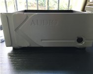
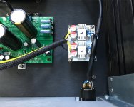
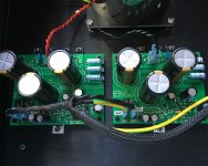
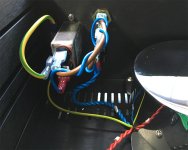
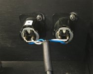
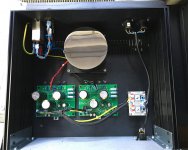
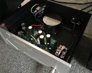
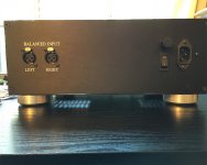
Some iPhone pics.
Enclosure is by Modu. I'm not sure why I went with the 3u enclosure. I think I just started with the height of my previous project and never went back to examine dimensions again. 🙁 2u would have been fine/better. I could have gone for a cabinet 5cm less deep as well. The circa €15 difference in base enclosure price would have been, however, rounding error to the cost of the enclosure post milling, engraving and drilling.
The power supply is from my previous project - 5A capable regulated PSU with superb line rejection. (I used 3 of these to build a linear ATX supply.) I just used a couple of the spare boards I had and downsized the filter caps a bit from 10,000uF to 6,800uF 🙂.
Attachments
- Home
- Amplifiers
- Headphone Systems
- "The Wire" Ultra-High Performance Headphone Amplifier - PCB's