Time / cost / complexity ... The Wire amps themselves are great little units, it just the implementation. I had a few problems with the dps-600's (I broke them) and my inexperiance started to show... As time moves on, motivation moves from one project to another and with it goes the money. I would like to complete this at some point this year, but it wont be in the next 3 or 4 months.
Paul
Paul
Last edited:
Owen,
Could I ask you if you think that Semlad's 8A 160v Alfet Mosfets, ALF08N16V/ALF08P16V, would be appropriate for a "less demanding" version of this amp, and if that would need any major design changes?
Could I ask you if you think that Semlad's 8A 160v Alfet Mosfets, ALF08N16V/ALF08P16V, would be appropriate for a "less demanding" version of this amp, and if that would need any major design changes?
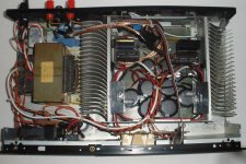
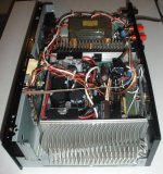
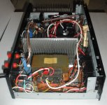
here are some pics. This is a 2 channel version, single ended input, one pair of output fets per channel. When I first saw the bare amp boards I thought it would be a piece of cake to put them into an old kenwood chasis. Boy was I wrong. I kept adding stuff and I had less and less room. To change a part on the amp boards now takes 1-2 hours of dissassembly and then reassembly. I was going to use one power supply for the front end and the outputs with 6 x 10,000uf caps. I was looking around ebay one day and came across some epoxy cast transformers 0-15, 0-15, 200ma output. I thought the transformer would fit perfect. It did. I had a bit of trouble adding another bridge rectifier and 2 more caps. There was a bit of space on the powersupply board to add a +24v supply for the front panel VU led display. It didn't take too much effort to add a couple more +/- 75v regulators for the LME front end. I moved the DC protect/speaker relay board to the rear heatsink bracket. I found a couple of socket fuse holders that had room inside for 10ohm resistors so I could check the bias whenever I needed to. I tried to keep the leads as short as possible, but I had to make some of them a bit longer to make service easier. I had too much trouble to twist the 14 guage power wires so I left them straight. Why did I use 14guage, because I had some. I added some output zobels and a coil near the speaker binding posts. You can see the epoxy transformer just below the transformer in the first photo and the socket fuse holders with the resistors just above the filter caps.
The build was not without grief, what looked like 120khz osscilation was an old CFL lamp on the work bench. Little 68khz pulses was the battery charger for my hand drill. A 10.6 mhz osscilation was the heatsinks not grounded. A 1.25 mhz oscilation was the output caps I forgot to put on the lm3xx regulators. I put 10uf close to the regulators and oscilation gone. I had a ground loop buzz when hooking up a cd player to play some music. I removed the 0 ohm jumpers on the boards to solve that one. I don't know what it sounds like as it is playing through some junk speakers.
With +/- 65 volts on the fets and +/-75 volts on the front end, power is a hair over 150 watts @7.5 ohms per channel just before clipping. My load resistors are 2.5 ohms. If you remember a few posts back I changed the feedback and input resistors to 30k ohm. I kept the original caps 330uf and the bandwidth at 10 watts is flat from 1hz to forever. I say forever as my generator only goes to 110khz. Before I put on the output coils and zobel, full power bandwidth was past 60khz with some obvious slewing above 100khz
The powersupply board is a single sided circuit board that I removed copper with a dremmel tool as needed. You can see where the dremmel tool slipped on the rear of the amplifier as I was trying to enlarge a hole for the fuse holder.
The amplifier has been playing on the workbench for a couple of days now and I will hook it up to the livingroom speakes when the wife is not home. She retired over the holidays and for some reason I don't have much free time lately.
Attachments


..
Would that 0.22 or 0.33 not be swamped by the 6Ω(?) resistance of each mosfet? I looked at the data sheet but there's nothing there about resistance.
The use of sorce resistors has nothing to do with the Drain-Source resistance of the used transistors. Source or Emitter resistors are used for thermal stability. You can read all about design considerations in this article:
http://products.semelab-tt.com/pdf/ApplicationNoteAlfet.pdf
Owen,
Could I ask you if you think that Semlad's 8A 160v Alfet Mosfets, ALF08N16V/ALF08P16V, would be appropriate for a "less demanding" version of this amp, and if that would need any major design changes?
Amazig, they can make a pdf file with no info on the pinout. Is that follow the Hitachi schema, or is the drain pin#2 ?
The Pin Out is specified.
You just need to read the pdf Datasheet more fully.
Thanks, last line.
The wife went out shopping today so I was able to hook up the amp to the living room speakers and do some listening.
PFG is my immediate inpression.
Thanks Owen
PFG is my immediate inpression.
Thanks Owen
Hey Mark, How's Quatar
Pretty F_c_i_g Good is case you didn't understand Mark,
but I know you did
Pretty F_c_i_g Good is case you didn't understand Mark,
but I know you did
Freezing my butt off with you buddy. Can't wait to hear it myself. I'm putting together the amp chassis over the next few Weeks. Will probably turn into months. But forward movement at least.
Well guys, I went to the dark side (NCore). Not regretting it. 0.0003% THD+N at 50 watts is not too shabby.
Hi FloridaBear,
Great stuff,
Need some education, you mean a "NCore" transformer? and this would make a difference in THD compared to say a torodial core or a regular "E" laminated core?
What test equipment are you using to measure this low value of THD?
Thanks
Rick
Great stuff,
Need some education, you mean a "NCore" transformer? and this would make a difference in THD compared to say a torodial core or a regular "E" laminated core?
What test equipment are you using to measure this low value of THD?
Thanks
Rick
Not sure what FloridaBear's post has to do with The Wire. Did you build/listen/compare The Wire to the NCore?
I purchased and tried to build a pair of Wire amp boards but it proved to be beyond my meager skills. The NC400 build seemed to be the best way for me to get an ultra-low distortion amp. I was just posting as a "happy ending" to my Wire adventure.
- Home
- Amplifiers
- Solid State
- "The Wire AMP" Class A/AB Power Amplifier based on the LME49830 with Lateral Mosfets