Sure, but then there’s a discharge path of the same nature when reading the SH, not to mention the capacitor leakage. Sampling the reference and assuming it will Hold forever, until next restart looks like a weird idea to me.
You just connect the input of the output buffer straight to the hold capacitor, no need for extra switches.
Gate and capacitor oxide leakage can be very small when the oxide is thick enough, otherwise EPROMs and flash memories couldn't work. You could also keep the PMOS biased slightly on to make its resistance more predictable and process- and temperature-independent. To get a cut-off frequency below 1 Hz with a capacitance that still fits on chip, say 100 pF, you need an on resistance of at least 1.6 Gohm. You get that in weak inversion at the same VGS that would give a saturation drain current of at most 16 pA.
Gate and capacitor oxide leakage can be very small when the oxide is thick enough, otherwise EPROMs and flash memories couldn't work. You could also keep the PMOS biased slightly on to make its resistance more predictable and process- and temperature-independent. To get a cut-off frequency below 1 Hz with a capacitance that still fits on chip, say 100 pF, you need an on resistance of at least 1.6 Gohm. You get that in weak inversion at the same VGS that would give a saturation drain current of at most 16 pA.
Last edited:
Packaging and connections
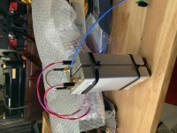
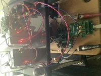
Some solutions I’m exploring. I strapped the clock and a doubler together with the tops of the cases compressing a conformal pad. This stops any vibration of the lids and dampens the whole unit quite nicely. Added special soft feet to the edge so that the actual xtall rests in an on edge, rather than flat orientation surrounded by foam inside to stabilize air currents and thus temperature. In the next picture a Twisted Pear Cronus was assembled in inverted order such that the Cronus board is on top. I also mounted the jumpers on the bottom to provide unobstructed mounting of the squaring circuitry. The sound is so wonderful that I haven’t moved it from the actual breadboard into a case yet.
Sorry I don’t know how to rotate pictures.


No sand in the boxes? Too bad, that would definitely improve the sound.
Sand from the Kalahari desert has a special sonic signature and it is highly recommended. No Nevada, Mururoa atoll or Kazakhstan sand, that could be slightly radioactive and affect the sound by ionizing the air between the sand grains.
Sand from the Kalahari desert has a special sonic signature and it is highly recommended. No Nevada, Mururoa atoll or Kazakhstan sand, that could be slightly radioactive and affect the sound by ionizing the air between the sand grains.
Sorry I don’t know how to rotate pictures.
Pictures that rotate unintendedly are often related to the EXIF header of modern JPEG files, which is supported by some programs and not by others. I usually solve it with a free command line program called jhead, giving the command jhead -autorot *.jpg or jhead -purejpg *.jpg
No sand in the boxes? Too bad, that would definitely improve the sound.
Sand from the Kalahari desert has a special sonic signature and it is highly recommended. No Nevada, Mururoa atoll or Kazakhstan sand, that could be slightly radioactive and affect the sound by ionizing the air between the sand grains.
Maybe the sand of the Kalahari desert could even improves your oscillator.
You should give it a try.
No sand in the boxes? Too bad, that would definitely improve the sound. /QUOTE]
I am happy to try real suggestions, that is actually give them a listen. Ears are both the most sensitive tools that I own and the ones that really matter to me. Have you actually tried filling the box with sand? I would be potentially concerned about both salt and metallic impurities in most sand. Finely ground and washed quartz crystals would provide a nice rf blocking and have been beneficially applied in a few commercial and scientific implimentations. Still I believe you are referring to filling another box that surrounds the clock boxes with sand, not having the sand in contact with the inductors and circuit traces.
Syn08, would you be willing to share pictures and descriptions of your implementation of the clocks? Have you made any measurements of anything that does affect the clocks performance, that could be inexpensively explored by those of us interested in this hobby? Sarcasm is fun when not mean spirited but I for one am here to share insights with fellow audio enthusiasts. To learn from others explorations and to work together toward ever improving our enjoyment of music by refining our audio reproduction equipment. I also have made no claim that anything I have done has unambiguously improved the actual or subjective performance of the clocks. First principle extrapolation would suggest reducing external vibration, minimizing temperature variation, shortening wiring paths all could be beneficial and would at least not be detrimental.
I am sure that he has already tried that and of course with a subsequent double blind test. is there a shop that sells Kalahari sand? I couldn't find one yet.Maybe the sand of the Kalahari desert could even improves your oscillator.
You should give it a try.
hi Andrea_mori,
may i ask if the clock can be applied to i2soverusb?
I am interested if any kind diyer can share his experience...
may i ask if the clock can be applied to i2soverusb?
I am interested if any kind diyer can share his experience...
"may i ask if the clock can be applied to i2soverusb?"
Yes, I've done it. However I2SoverUSB requires 45/49 MHz external clocks. For some dac chips that might be fine. For other chips maybe some other circuitry would have to be designed so everything can run synchronously.
Yes, I've done it. However I2SoverUSB requires 45/49 MHz external clocks. For some dac chips that might be fine. For other chips maybe some other circuitry would have to be designed so everything can run synchronously.
I am using the i2soverusb to ad1862. It is good. Thinking if applying better clock such as andrea's clock will further improve the sound quality.
How is your result? Can you kindly share?
How is your result? Can you kindly share?
Result is good, easily sounds better to me than using I2SoverUSB clocks. However, my dac chip needs 22/24MHz clocks, so I used a frequency multiplier chip to produce the 45/49 MHz clocks needed by I2SoverUSB. Then I reclock I2S signals coming out of I2SoverUSB to attenuate any jitter caused by the frequency multiplier. Also, I found that using Andrea's clocks at 11/12 Mhz (along with Andrea's frequency doublers) produced slightly better sounding (to me) 22/24MHz master clocks, as opposed to earlier having tried Andrea's clocks directly with 22/24 Mhz crystals.
Last edited:
You can run I2susb with 22/24 after a firmware change, if you are ok with a max sample rate of 176/192.
I am interested in this mod as well. I was considering to feed Andreas clock via the external oscillator board and STS but the high frequency rate 45/49 made me discard it, I just have the 5/6 and two doublers. However I didn´t know that frequency could be changed after a firmware update, would it be possible to use 11/12??
Actually I wanted to mod the usb hub controller using the 24Mhz external clock (NS3) of my usb card but I think it is SMSL USB3317 that uses 26Mhz, so no go....
Actually I wanted to mod the usb hub controller using the 24Mhz external clock (NS3) of my usb card but I think it is SMSL USB3317 that uses 26Mhz, so no go....
Could someone describe what is meant by I2S over usb? I thought that usb had its own clock and that audio stream(s) were packeted to travel over it. I have experience with a usb to I2S converter that derives its audio clocks from the usb master clock. Yes improving the usb clock made a difference, but switching to a fifo or an amenero that could be fed external audio master clock sounded far superior to any improvement in the usb clock, while rendering such improvements to the usb clock moot.
"Could someone describe what is meant by I2S over usb?"
Its all one word: I2SoverUSB -- I2SoverUSB - I2S over USB Audio
Its all one word: I2SoverUSB -- I2SoverUSB - I2S over USB Audio
Yes - my apologies for the typo, it's as Mark said, the JL sounds implementation. They can supply modified firmware to run off 22/24, I think a jumper connection may need to be made as well, but best enquire with Lyuben at JL.
Hi Andrea,
is there a reason why you are using a buffered 74AC04 inverter in the TWTMC-STS? I swapped it for a 74LVCU04 and the output signal looks much better with it.
is there a reason why you are using a buffered 74AC04 inverter in the TWTMC-STS? I swapped it for a 74LVCU04 and the output signal looks much better with it.
Hi Andrea,
is there a reason why you are using a buffered 74AC04 inverter in the TWTMC-STS? I swapped it for a 74LVCU04 and the output signal looks much better with it.
Yes, we have used the 74AC04 because it has the best phase noise performance.
We have tried almost all logic families and the AC was 10-15 dB better.
And not all the brands, TI and On-Semi devices have worse phase noise than the brand we have used.
Although someone think that the beaty of the waveform is crucial, it has nothing to do with the phase noise.
- Status
- Not open for further replies.
- Home
- Source & Line
- Digital Line Level
- The Well Tempered Master Clock - Building a low phase noise/jitter crystal oscillator