However if you have some extra space shuttle tiles maybe it can make a difference? Femtosecond Clocks The plot seems to be one that can be duplicated pretty easily and seems to show close in phase noise (no $150K test system needed) although you would need a pretty clean ADC to be sure of what you measure.
Well, I am just confused about the femto measurements 😀 Also did not find how this was really made. The DAC could be driven from a CD-Player with a related signal and then recorded by a sound card (ADC).
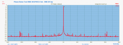
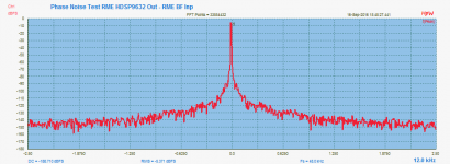
The pointed analysis pushed me to do some similar things as I did with a loop back test using the RME BabyFace using 33 mio FFT 😀.
For the new setup I used the RME HDSP as a DAC source and the RME BabyFace as the ADC using 12kHz Sine signal & 48kHz & 24 bit & 33 mio FFT points to have a Bin resolution of 1.43 milli Herz. The sample time is very long about 12 minutes!
Here the results 😀 indicates some symmetric side peaks and the bell closed to 12 kHz with the used 10 Term FFT Window...
Keep in mind that the jitter behavior is a combination of both sound cards...
Hp
Attachments

I thought about the MSB measurement and realized that its very close to BS. There are so many things to work out before its meaningful. For the traditional measurements the article about outlines all the corrections and variables needed and there are quite a few. This approach brings a fresh set.
First the measurement is usually in rtHz so the actual bandwidth of the analysis is corrected for. Then the relationship of phase noise in the output back to phase noise in the oscillator is not direct (that would be too easy). I am neither equipped to figure out the math or probably comprehend it all. I would take a known level of wideband phase noise added to an oscillator and see how it shows up in the output. Spurs are easy since they have a specific level but the broadband noise just gets lower when the resolution is increased.
On the ADC in the testing I did its phase noise seemed to drop out. I took a time mark generator, essentially a precision divider from an ovenized crystal, and divided down to 10 KHz and still got a single line in the spectrum. I will try again soon but it doesn't seem to be an issue, I don't understand why either.
MSBTech measurements
MSBTech are a real mixed bag with their measurements. You have to
question them constantly. A good example is their Select DAC, from the
user manual DR = 173dB, OP level = 10V PP, OP impedance = 75 ohm.
If you do the calcs with 20k BW / 10V PP / 75 ohm thermal noise - best
possible DR is 147dB. That's quite a difference!
The phase noise specs of Femto 33 appear to be on the edge of what is
currently possible - maybe not possible. Looking at NEL Freq Controls best
10 MHz OCXO which even slightly outclasses a Wenzel Blue Top - MSB's
24.567 Femtoclock is almost as good at more than double the freq.
Are they telling Porkies again (porky pies = lies)?
Who knows! Got to watch em. 🙂
I thought about the MSB measurement and realized that its very close to BS. There are so many things to work out before its meaningful. For the traditional measurements the article about outlines all the corrections and variables needed and there are quite a few. This approach brings a fresh set.
First the measurement is usually in rtHz so the actual bandwidth of the analysis is corrected for. Then the relationship of phase noise in the output back to phase noise in the oscillator is not direct (that would be too easy). I am neither equipped to figure out the math or probably comprehend it all. I would take a known level of wideband phase noise added to an oscillator and see how it shows up in the output. Spurs are easy since they have a specific level but the broadband noise just gets lower when the resolution is increased.
On the ADC in the testing I did its phase noise seemed to drop out. I took a time mark generator, essentially a precision divider from an ovenized crystal, and divided down to 10 KHz and still got a single line in the spectrum. I will try again soon but it doesn't seem to be an issue, I don't understand why either.
MSBTech are a real mixed bag with their measurements. You have to
question them constantly. A good example is their Select DAC, from the
user manual DR = 173dB, OP level = 10V PP, OP impedance = 75 ohm.
If you do the calcs with 20k BW / 10V PP / 75 ohm thermal noise - best
possible DR is 147dB. That's quite a difference!
The phase noise specs of Femto 33 appear to be on the edge of what is
currently possible - maybe not possible. Looking at NEL Freq Controls best
10 MHz OCXO which even slightly outclasses a Wenzel Blue Top - MSB's
24.567 Femtoclock is almost as good at more than double the freq.
Are they telling Porkies again (porky pies = lies)?
Who knows! Got to watch em. 🙂
Of course they would never lie. Ask Mark Brasfield about his experiece with his namesake company. And why he won't go near them.
However there is a buck to be made. . .
However there is a buck to be made. . .
Interesting digression...
I have taken a (very quick) look at the company and their products.
Solid level of engineering is apparent in their products. But I am puzzled by the presented measurements.
The (claimed) figures of their clocks - ie 114 dB at 1Hz for 24.576 MHz femto33 (no Phase Noise measurements as far as I could see) is
what I would describe as being truly the outermost limits of technical possibility today.
It is indeed a very serious claim...
Yet the HW implementation (HS size, enclosure design, electrical environment, etc) might be - according
to my limited knowledge and experience - incapable of delivering those figures, specially to the DAC chips.
Producing and measuring PN that low requires specialized testing procedures in a strictly controlled
testing environment, yet simple measurements by Spectralab SW is presented as evidence....
For that astronomic asking-price, it would be possible to out-source the design to some specialist manufacturer.
As mentioned earlier, there is a high level of structural, mechanical, and electrical engineering apparent in their products.
Last edited:
Producing and measuring PN that low requires specialized testing procedures in a strictly controlled
testing environment, yet simple measurements by Spectralab SW is presented as evidence....
This is clearly not the spectrum around 24.5 MHz but a tone of unknown frequency
that can be represented with a 44 KHz sample rate, as is displayed in the top right
of the FFT display. probably the output of a DAC.
That also means downsampling / frequency division by 25.4M / 44k = something
around 500.
Division by 10 brings 20 dB, by 1000 brings 60 dB, 500 is 6 dB less or 54 dB gain
by filtering / downsampling. which is probably more reasonable.
There is no spectrum analyzer on the market that could provide > 150 dB dyn.range at
24.5 MHz. And if there was one, its own clock would have to be even much better.
I cannot take that seriously, to formulate it extremely friendly.
Gerhard
Hi guys... havent had time to do electronics in a while due to renovations. I spent the afternoon shoveling concrete! Anyway, here are a few jitter hacks.
1) How much jitter on your I2S?
Play any 44.1k to 96k wave. Connect Wordclock to coax, into soundcard. Set soundcard to record at 192k and record the Wordclock directly. FFT it. There! You can measure I2S jitter alone, without the jitter added by the DAC itself.
Optionally, run the WCLK through a buffer...
2) Let's compare oscillators.
Pick two 1€ canned CMOS 3V3 oscillators. Power them from two AA batteries, each. Feed the outputs to a XOR gate (powered from another pair of AAs), then a lowpass. You get a beat frequency at the difference between oscillators frequencies.
Use brand new batteries, or slightly discharged ones to set the oscillator frequencies. Mess with it until you get a usable beat frequency, i.e. 50 Hz or more.
Acquire the beat tone with your soundcard, and FFT it. Optionally, plot frequency drift versus time, etc.
Amusing tidbit : taping a wad of kleenex tissues on the oscillator stabilizes air currents and therefore temperature, and produces a very noticeable reduction in LF phase noise (ie, short term drift). Poor man's OCXO, that is a cheap tweak! (although if you really insist, I might be convinced to sell you some cotton balls and a few inches of tape for $100).
Just suggesting some fun experiments you can do without any fancy gear. Results are uncalibrated of course, but the differences between 1€ canned oscillators of various models and brands were MASSIVE, and even better, reproducible!
😀
Last edited:
If you use an RF mixer Frequency Mixers - Mini Circuits you should get an even lower noise floor and once synced a cap will remove the DC and the dynamic range is much increased. Calibration is a challenge.
The cheap can oscillators probably don't need this level of tweak to sort.
I'll try word clock into an ADC. That seems almost too simple.
The cheap can oscillators probably don't need this level of tweak to sort.
I'll try word clock into an ADC. That seems almost too simple.
I'll try word clock into an ADC. That seems almost too simple.
Well, it is too simple:
- We are only interested in jitter at transitions (ie, edges)
- However this method also measures noise on the flat 0/1 levels on your wordclock. Noise outside of edges doesn't count for jitter. Adding a 74xx buffer in the measurement chain (powered by a low-noise source like 2x AA batteries) fixes this by ensuring the flat portions of the waveform are properly flat, and only the edge timing is measured.
Although... if there is noise on the flat portions of the waveform, and it comes from the power supply of whatever chip generates your clock being noisy, then you'd be interested in that, too... since power supply noise on a digital chip modulates the logic threshold voltage, and therefore, introduces jitter. Acquiring power supply noise with your soundcard while the system operates can be quite interesting, too...
Careful with this - not all DACs have the same reference clock.
For instance, older style DACs such as the TDA1541 use the word clock as reference, so this is the clock that must be jiter-less.
Some early bitstream DACs even used the bit clock as reference.
Most modern DACs use the master clock (MCLK) as reference and the jitter on the other lines is of no issue as long as the basic timing is followed according to spec - because the very first thing it does is re-clock everything with MCLK.
In other words, be careful how and what clock you generate to get best results, and of course what clock you measure - you might be measuring completely irrelevant signals.
Careful with this - not all DACs have the same reference clock.
I still do some research about the direct measurement using a pure signal. Well known is, that we test 2 systems DAC & DAC with it's components.
First on MSB Phase:
The given FFT minimal bin resolution is fs/FFT size what is about 0.183 Hz. There are some needles what indicate compressed spectrum pins to one pixel. Just drawing somewhere an 1Hz range is bocus.
Second about the MSB measurement idle spectrum noise about -200dB:
May the missed to resale to dBFS using the external amplifiers.
Now as Gerhard mentioned there is some attenuation going on, what could be multiplied back (freq. scale). But requires the required factor what is may implementation dependent PCM or DSD and also oversampling.
One simple test would be to alter the oscillator master freq. by 10ppm and measure the resulting playing signal frequency shift on the used signal as for instance by a signal as fs/4. 😀
Hp
Thank you all for your recommendations.
I believe these are some great ideas to evaluate the performance of Andreas clocks before PN measurement equipment is available.
I contacted my local university and asked to be given acess to the R&S Signal analyzer at the dept of Signals & Systems.
Unfortunately it was denied (I applied 4 times).
I'm sure Gerhard can perform a couple of quick measurements if he's willing.
Otherwize I'd like to know if Andrea or anyone else would be able and willing to try simple jitter measurements as done in MSB (audio dac + dut + soundcard).
Cheers.
Otherwize I'd like to know if Andrea or anyone else would be able and willing to try simple jitter measurements as done in MSB (audio dac + dut + soundcard).
Cheers.
I could do the measurements with my DC-receiver at 11,... Mhz.
Herbert.
I could do the measurements with my DC-receiver at 11,... Mhz.
Herbert.
----------------------------
Hello Herbert and thank you for the offer.
I think that would be a very good idea.
It would be very instructive to perform some measurements before Andrea can access the HP Signal Source Analyzer.
You'll need a couple of finished boards + xtals (Pierce + Emitter Coupled) ofcourse.
I hope Andrea would be able to provide some assistance here...
I dont know what frequencies are available....we need Andrea's feedback on this.
Herbert,
you have the Laptech AT-Cut at 11.2896 MHz that I sent you. You have also the Clapp board.
If you think to measure the oscillators I could send you the other 2 boards available, the Pierce and the Driscoll.
Please, let me know.
Andrea
------------------------------------------------------------Herbert,
you have the Laptech AT-Cut at 11.2896 MHz that I sent you. You have also the Clapp board.
If you think to measure the oscillators I could send you the other 2 boards available, the Pierce and the Driscoll.
Please, let me know.
Andrea
Thanx Andrea.
This is excellent cooperation.
Although Rutgers oscillator has been measured previously, it would be informative to compare the three circuits with the same xtal.
Three boards + the same crystal.
Andrea, have u had the time to revise the Pierce yet?
Yet another comparison: Colpitts-Clapp vs Driscoll OCXO
I have just finished to build the DAC for my friend's audio system on the wood proto-table, so I took the opportunity to do a listening comparison between the Colpitts-Clapp and the Driscoll OCXO. The DAC need a master clock at 11.2896 MHZ, so I used the Laptech AT-Cut for the Clapp and the Laptech SC-Cut for the Driscoll.
This is my subjective impression: although both oscillators perform very very good, the Driscoll sounds clearly better, the best I have tested until now.
Bass are more dumped and deeper, female voices are warm and clear, more transparent, middle range is superb, high are more detailed but never aggressive, soundstage is wider and deeper. Listening to unplugged music the differences are more evident, with the Driscoll the music scene is absolutely realistic.
A little off topic: this dac sounds truly impressive, one of the best I have ever heard.
Attachments

...the Colpitts-Clapp and the Driscoll OCXO....
...both oscillators perform very very good, the Driscoll sounds clearly better, the best I have tested until now.
Very interesting results.
We know that the RutgerS oscillator has the 3 series-stages of 74HC04 based slicers.
How about the Emitter coupled osicllator? Does it have the same slicer section as the RutgerS?
...A little off topic: this dac sounds truly impressive, one of the best I have ever heard.
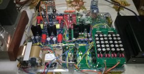
What is this DAC kit? It contains a lot of components.
Cheers
- Status
- Not open for further replies.
- Home
- Source & Line
- Digital Line Level
- The Well Tempered Master Clock - Building a low phase noise/jitter crystal oscillator