I would think that adding the extra components to Andrea's dual Driscoll to implement the block diagram should not be too difficult, especially if the noise floor of around 1 nV/rtHz of an LME49990/AD797/LT1024 would be low enough.
If you guys need LT1028, I'd love to donate some of it. Just let me know.
Poting
Hi ... interesting exchange here ... just a brief comment/suggestion (don't know if it's feasible in this context, though):
How about the AD8099? Very low noise and low THD both at low frequencies and somewhat up.
Cheers,
Jesper
especially if the noise floor of around 1 nV/rtHz of an LME49990/AD797/LT1024 would be low enough.
How about the AD8099? Very low noise and low THD both at low frequencies and somewhat up.
Cheers,
Jesper
There is something wrong with a crystal oscillator if you can measure its phase noise with a spectrum analyzer.
Phase detectors can generate high levels of phase noise. Long ago I used to use the MC4044 phase detector in RF synthesisers and it turned out that the D type based phase detector had a dead zone causing the thing to constantly hunt to and fro, modulating the VCO
Phase detectors can generate high levels of phase noise. Long ago I used to use the MC4044 phase detector in RF synthesisers and it turned out that the D type based phase detector had a dead zone causing the thing to constantly hunt to and fro, modulating the VCO
Are you setup to plot the Jtest output of a DAC with the different oscillators? I think it would be really interesting to see if it shows anything meaningful.
I don't own an FFT, can you suggest a suitable soundcard and the right software (cheap) to do the test? Or other inexpensive gear to do this?
For audio I'm not convinced that noise above 100 KHz is all that important. it is for other applications. The importance of close in noise is what is being explored here so response to 10 Hz or less is important. In this context a soundcard would be adequate.
I believe that a bandwidth from 1 Hz to 100 kHz is more than enough for audio.
I would think that adding the extra components to Andrea's dual Driscoll to implement the block diagram should not be too difficult, especially if the noise floor of around 1 nV/rtHz of an LME49990/AD797/LT1024 would be low enough.
We could use the Driscoll at 22/24 MHz with harmonic SC-Cut crystals, since they have a Q around 500k, a good starting point for the Driscoll oscillator that maximizes the loaded Q. Adding the VCO capability.
2) Could we start with 24.568/22.5792 MHz and a multiplier/divider for all the variations? or do we need discrete oscillators for each frequency?
To keep the project not too complicated would be better starting with two frequencies (22/24) dividing by 2/4 and multiplying by 2/4. D-type flip-flop could easily do the division job. I ask Gerhard about the best way to do the multiplication job.
Phase noise measurement tool
I have just started a new thread about the opportunity of building a phase noise measurement system:
http://www.diyaudio.com/forums/equi...urement-system-digital-audio.html#post4812029
Please, use the above, leaving this thread related to oscillators only
I have just started a new thread about the opportunity of building a phase noise measurement system:
http://www.diyaudio.com/forums/equi...urement-system-digital-audio.html#post4812029
Please, use the above, leaving this thread related to oscillators only
I have just done one more test with another oscillator that confirm the previous session.
- TWTMC-P Pierce with budget HC-49/U AT-Cut crystal from TFC powered by the on-board Aune regulator
...Again the crystal makes the difference....
Not necessarily true.
Good testing and report btw.
Cheers.
Last edited:
@Andrea .. Just a quick question with respect to the Pierce oscillator: Building the Pierce oscillator and supplying it from 6.7 volts - would that be ok? And can I use the components specified in your TWTMC-P for the 6.144 MHz version?
Have a good weekend ...
Cheers,
Jesper
Have a good weekend ...
Cheers,
Jesper
There is something wrong with a crystal oscillator if you can measure its phase noise with a spectrum analyzer.
Phase detectors can generate high levels of phase noise. Long ago I used to use the MC4044 phase detector in RF synthesisers and it turned out that the D type based phase detector had a dead zone causing the thing to constantly hunt to and fro, modulating the VCO
Really high performance spectrum analyzers can show phase noise in inexpensive crystal oscillators but not at this level.
The phase detector I linked is a special double balanced mixer designed for high DC out per the data sheet so it should be well suited to this task.
@Andrea .. Just a quick question with respect to the Pierce oscillator: Building the Pierce oscillator and supplying it from 6.7 volts - would that be ok? And can I use the components specified in your TWTMC-P for the 6.144 MHz version?
Have a good weekend ...
Cheers,
Jesper
You have to use an unbuffered '04 7V tolerant.
The parts value in the BOM are OK for 6.7V, power dissipated in the crystal is around 100uW.
You have to use an unbuffered '04 7V tolerant.
The parts value in the BOM are OK for 6.7V, power dissipated in the crystal is around 100uW.
Thanks Andrea for your prompt reply - very helpful ;-)
Jesper
This is the TWTMC-AIO All in one combo oscillators.
There are 2 Driscoll oscillators at 22.5792 MHz and 24.576 MHz and 2 shunt regulators at 6V and 3V3.
It needs only a 9 to 12VDC unregulated or pre-regulated power supply.
Crystals are HC-49/U fundamental from TFC (Laptech's sister). Their specs are very good for a budget crystal in resistance welded package.
The board can be upgraded with Laptech HC-43/U crystals without any changing of the other parts.
Hi Andrea.
Kudos on your nice work.
The inverter-based Pierce is selling it short.
Logic devices are not designed for:
- linear amplification,
- low noise figures (as amps)
- or "buffering".
They should only be used for their designed purpose: high SR pulse generation.
The Pierce uses the crystal as a bandpass + feedback element: this is a powerful combination for lower frequency oscillators.
A correctly-designed Pierce will easily outperform even the Driscoll @ say <20 MHz, due to its circuit features.
Stay away from multiple cascaded or parallelled gates for "buffering". They are not buffers & will not work as such.
Keep up the good work gentlemen.
Last edited:
...A correctly-designed Pierce will easily outperform even the Driscoll @ say <20 MHz, due to its cicuit features....
I just noticed a slight mistake in my text above.
What I meant to say was:
"A correctly-designed Pierce will even be able to outperform the Driscoll @ say <20 MHz, due to its circuit features."
This was actually tested at the lab back in 2010.
Measurements were also performed on an Inverter-based Pierce, (same xtal) and its performance was far worse.
-----------------------------------------------------------------
Keep up the good work gentlemen.
...
...
Alexiss .. I read what you are writing and I have no doubt that you have both experience and knowledge in this field ... But personally I have this feeling of being the rabbit tempted with a carrot that it cannot reach ... Any chance you can be specific about which alternatives you would suggest?
BTW I am concluding laying out a Pierce oscillator today (according to Andrea's design) and so if you have suggestions for changes I'd appreciate if you can share them in due time.
Cheers,
Jesper
..."A correctly-designed Pierce will even be able to outperform the Driscoll @ say <20 MHz, due to its circuit features."
...
...Measurements were also performed on an Inverter-based Pierce, (same xtal) and its performance was far worse.
Alexiss .. I read what you are writing and I have no doubt that you have both experience and knowledge in this field ... But personally I have this feeling of being the rabbit tempted with a carrot that it cannot reach ... Any chance you can be specific about which alternatives you would suggest?
BTW I am concluding laying out a Pierce oscillator today (according to Andrea's design) and so if you have suggestions for changes I'd appreciate if you can share them in due time.
Cheers,
Jesper
Thankfully there are many more knowledgable people here.
My recommendations on the Pierce is a discrete design, with a disrete buffer - yes, a buffer, not an inverter used as such.
I think I saw one in a book recently. Just google it & if u dont find anything, let me know.
The Inverter-based Pierce is ok for u-processors, but not for high performance design that people crave on this thread.
Pierce has, in my opinion, the best performance <20 MHz with normal transistors. It is an deceptively simple circuit, but dont be fooled.
Colpitts and Driscoll are very good but not as good as Pierce at low f.
I know Herbert does not agree, and i'm willing to listen to him, he is very knowledgable in osc design.
Hi Alexiss ... Thanks for your prompt response and suggestion.
Hmmm ... as it is I will admit to not having the discernment in this field that will (quickly) allow me to sort between the circuits I find when googling. Also, as it is the Pierce circuitry Andrea has suggested won't feed a very long path - it goes into a divider which I reckon also has quite a say in the final quality of the oscillator.
Here I use a FF - but am a bit unsure of which FF to choose - but guessing that one of the reasons why Herbert's oscillator achieves these fine phase noise figures may be due to the high voltages I most likely will use the same series FF (i.e. an HC74 version) and feed it a high voltage.
However, if you or one of the other "oscillator insighters" here has a better suggestion I'm all ears (although - as I wrote - I'm wrapping up this layout today).
Cheers,
Jesper
What is your oscillator frequency?
So you'd like to divide it to lower f with flip/flops?
Could u post a rough sketch of your idea.
So you'd like to divide it to lower f with flip/flops?
Could u post a rough sketch of your idea.
Hi Alexiss ... Thanks for asking ...
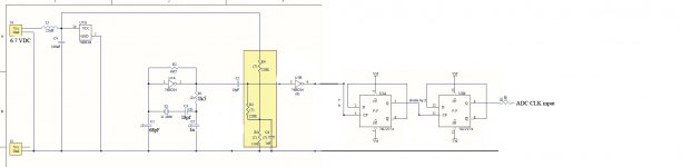
I basically use the circuitry that Andrea has outlined in his TWTMC- D&D (link here:
http://www.diyaudio.com/forums/digi...itter-crystal-oscillator-123.html#post4759763 - top part of schematic on P. 2)
i.e one dual FF IC (74LVC74 or 74HC74) to make the division. The Pierce circuitry also is similar to Andrea's although with some layout changes. I don't use any resistors between the 74HC(U)04 and the FF input - the track length is about 34 mms. Following the FF there are resistors to the ADC inputs. Supply voltages are 6.7 - 6.8 VDC.
I hope this gives an idea about the setup I intend ... Might you have any ideas/suggestions?
God dag herfra 😉
Jesper
The crystal is a 6.144 MHz AT cut from Laptech (courtesy Andrea) which I then divide by /2/2 (i.e. 4) to arrive at 1.536 MHz.What is your oscillator frequency?
I basically use the circuitry that Andrea has outlined in his TWTMC- D&D (link here:
http://www.diyaudio.com/forums/digi...itter-crystal-oscillator-123.html#post4759763 - top part of schematic on P. 2)
i.e one dual FF IC (74LVC74 or 74HC74) to make the division. The Pierce circuitry also is similar to Andrea's although with some layout changes. I don't use any resistors between the 74HC(U)04 and the FF input - the track length is about 34 mms. Following the FF there are resistors to the ADC inputs. Supply voltages are 6.7 - 6.8 VDC.
I hope this gives an idea about the setup I intend ... Might you have any ideas/suggestions?
God dag herfra 😉
Jesper
- Status
- Not open for further replies.
- Home
- Source & Line
- Digital Line Level
- The Well Tempered Master Clock - Building a low phase noise/jitter crystal oscillator