Hello,
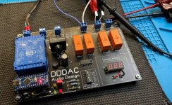
The manual does not show or tell if the external part of the DC input connector is connected to the chassis or not!
What do you consider the minimum internal height to have the clock and the frequency doubler boards wrapped in foam inserted into the '' tube ''?
Greetings, Eduard
P.s If an old co worker will make the '' containers '' for me it wont be difficult to add let us say 4 mm extra aluminium on to the tubes where these are opposite each other. This will be easier than creating extra distance.
When you lock the SMA connector the DC plug touches the case, this is the normal condition using the Hammond box.
The height of the DRIXO board is around 15mm, so you can add something less than 15mm to the height of the foam you are planning to use.
Boards size
DRIXO
151x75x15 mm (add 12mm for the SMA connector to the long side)
DBM
99x75x11 mm (add 12mm for the SMA connector to the long side)
DRIXO
151x75x15 mm (add 12mm for the SMA connector to the long side)
DBM
99x75x11 mm (add 12mm for the SMA connector to the long side)
couple variants of BOX-es for DRIXO from aliexpress:
* Enclosure Electronic Controller DIY Circuit Board Project Aluminum Box Cooling Case Sand Black Bend Plate 55 x 106 x 200mm|Wire Junction Boxes| - AliExpress
* New 1 PC Aluminum Junction Box PCB Instrument Enclosure Electronic DIY Electronic Project Case|Wire Junction Boxes| - AliExpress
* Black Aluminum Waterproof Enclosure Explosion proof Electronic Project Instrument Case Project Box Outdoor Junction Housing|Wire Junction Boxes| - AliExpress
Hello,
I just ordered 6 of these in Germany.
Enclosure DC-DD :: Diecast Aluminum :: Enclosures Boxes :: Electronic Parts :: Banzai Music GmbH
They look very similar to the Hammond ones. The Hammond however use 6 screws to close the box. They are deep enough for the Drixo and more than deep enough for the DBM circuits.. . But i think 6 identical boxes next to each other will look nicer.
There is no coating or paint so no need to scratch things to achieve good screening. One review ( elsewhere) mentions a good enough screening to make a mobile stop working. He had a Samsung and an Apple, one stopped the other didnt. Of course can increase thickness of the box by attaching a sheet or a U shaped panel in the clock area. Probably the complete board will try to communicate with neigbours.
If it surely wont make things worse it will be cheap to just add aluminium. It will at least make things more soundproof.
I found a document on shielding. Most of it is to difficult for me but i read it will better for shielding if the enclosure it not '' floating '' SO where to connect them too without getting into trouble?
Greetings, Eduard
Attachments
Hi Andrea.
I have received my 5 TWTMC-PXO-AIO-SF boards, but one of the electrolytes has fallen off during packing or transport. The pcb`s soldering points or the electrolytes legs doesn`t appear to have been damaged, but I hope that all the other components are soldered properly, otherwise there will be a lot of troubleshooting. ;o)
The 5 6.25 MHz crystals have each a number written on their back, but that has no practical significance, does it?
Is there a BOM to a 6.25MHz TWTMC-PXO-AIO-SF board or can the BOM to the
TWTMC-PXO-AIO-SF_6125_12500_25000_Mouser_BOM get used?
I may have overlooked this info, but is there a Mouser order number on The TWTMC-STS-SX board SMA connector at it`s pcb?
Is there a good Sine to Square wave U.FL cable from the Sine to Square Wave converter to for example a Buffalo BS GS2016 clocks pcb and how long must it be?
Last edited:
Hi Andrea.
I have received my 5 TWTMC-PXO-AIO-SF boards, but one of the electrolytes has fallen off during packing or transport. The pcb`s soldering points or the electrolytes legs doesn`t appear to have been damaged, but I hope that all the other components are soldered properly, otherwise there will be a lot of troubleshooting. ;o)
The 5 6.25 MHz crystals have each a number written on their back, but that has no practical significance, does it?
Is there a BOM to a 6.25MHz TWTMC-PXO-AIO-SF board or can the BOM to the
TWTMC-PXO-AIO-SF_6125_12500_25000_Mouser_BOM get used?
I may have overlooked this info, but is there a Mouser order number on The TWTMC-STS-SX board SMA connector at it`s pcb?
Is there a good Sine to Square wave U.FL cable from the Sine to Square Wave converter to for example a Buffalo BS GS2016 clocks pcb and how long must it be?
Hi,
I apologize for the issue, maybe the capacitor was not well soldered from the manufacturer and then it has fallen during transport.
I don't believe there was something damaged, can you resolder the capacitor?
I thought I have published the BOM but I'm not sure, so I attach it.
A suitable SMA connector for the TWTMC-STS is Molex 73391-0070 Mouser part 538-73391-0070.
To source U.FL cable I suggest Superbat (RfSupplier), they make custom cables as you want.
Keep it as short as possible.
Attachments
Hi,
I apologize for the issue, maybe the capacitor was not well soldered from the manufacturer and then it has fallen during transport.
I don't believe there was something damaged, can you resolder the capacitor?
I thought I have published the BOM but I'm not sure, so I attach it.
A suitable SMA connector for the TWTMC-STS is Molex 73391-0070 Mouser part 538-73391-0070.
To source U.FL cable I suggest Superbat (RfSupplier), they make custom cables as you want.
Keep it as short as possible.
Yes, yes 😉 I can solder...it`s the SF boards.
You have published the BOM, because I already have the attached.
I asked about it because the 6.25MHz wasn’t mentioned in the BOM`s name.
Thanks for the U.FL info. Does a good squarewave U.FL cable need to be over 3Ghz or which will be the best Ghz area?
Hi,
Laptech told me they should ship and the end of this month, so I believe I can ship the second week of June.
Sorry again for the delay.
Andrea
Laptech told me they should ship and the end of this month, so I believe I can ship the second week of June.
Sorry again for the delay.
Andrea
Hi,
Laptech told me they should ship and the end of this month, so I believe I can ship the second week of June.
Sorry again for the delay.
Andrea
Thanks for the update and it’s not your fault 🙂
Hello ,
For the UFL we can use the thin cable that is also use to connect the FIFOPI to the I2S input on the DDDAC board.
For the cable arriving at the terminals from the clock circuitry we will need the RG400.
On the fifopi board at the '' clock position '' there are two small boards connected to each other and then connected to the Fifopi.
The STS can be soldered to the 4 pins on the fifopi after removing these tiny boards.
Doede just published info about the board i asked him to make. I will use it for '' feeding '' the 61,7F cap that will be connected to the 6 .. clock related boards''
Do the STS boards have a terminal for connecting the 3,3 volt?
Greetings, Eduard
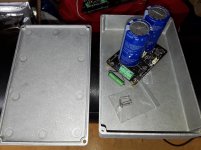
P.s also got the die cast aluminium stomping boxes. A bit more basic looks but i expect better screening
For the UFL we can use the thin cable that is also use to connect the FIFOPI to the I2S input on the DDDAC board.
For the cable arriving at the terminals from the clock circuitry we will need the RG400.
On the fifopi board at the '' clock position '' there are two small boards connected to each other and then connected to the Fifopi.
The STS can be soldered to the 4 pins on the fifopi after removing these tiny boards.
Doede just published info about the board i asked him to make. I will use it for '' feeding '' the 61,7F cap that will be connected to the 6 .. clock related boards''
Do the STS boards have a terminal for connecting the 3,3 volt?
Greetings, Eduard
P.s also got the die cast aluminium stomping boxes. A bit more basic looks but i expect better screening
Attachments
No......
Do the STS boards have a terminal for connecting the 3,3 volt?
..... powered by the fifopi
Do the STS boards have a terminal for connecting the 3,3 volt?
..... powered by the fifopi
Hi Eduard,
There is no terminal for Power. It is supplied through the power and ground pins that would power any standard 8 or 14 pin time base. If you are going to power the STS directly be sure not to connect the power pin to the fifopi but do connect the ground pin. Otherwise the normal clock power from the FIFOPI will power the STS.
I am unclear what the purpose of the 10K resister is in your picture unless it is just there for testing. It will not drain ian's ultra cap as the output is disconnected when the input power stops. As recharging can take several minutes from a totally discharged state, why would you want to fully discharge the ultra cap? Also you will need to disconnect the STS and anything else powered by the ultra cap if you do fully discharge it, as the current will go up as the voltage drops and the circuitry will not be happy under these conditions.
No......
Do the STS boards have a terminal for connecting the 3,3 volt?
..... powered by the fifopi
Hello,
I remember Andrea telling that you could improve things by giving the sts boards their own power supply.
Greetings,Eduard
No......
Do the STS boards have a terminal for connecting the 3,3 volt?
..... powered by the fifopi
You can power the STS by the FifoPi, just install the four pins and plug the board to DIL socket.
Hello Stephen,
I always discharge caps because the man who sold them wasnt sure if he did.
We will wait for Andrea to tell up about the 3,3 volt supply.
Greetings,Eduard
I always discharge caps because the man who sold them wasnt sure if he did.
We will wait for Andrea to tell up about the 3,3 volt supply.
Greetings,Eduard
Hello Andrea,
But you did mention you could use a separate supply to feed the two STS boards? If so, how to do this?
Greetings,Eduard
But you did mention you could use a separate supply to feed the two STS boards? If so, how to do this?
Greetings,Eduard
Hi Eduard,
if you want use separate power supply for the STS you should not install the Vcc pin and then you can connect the external 3V3 (or 5V) to the Vcc pad and the power ground to the GND pad.
If you want the STS boards don't fit the FifoPi you have to use the STS pad to connect the FIFO board (Vcc, GND, Out).
Please, take a look at the STS board PCB layout in the User manual.
- Status
- Not open for further replies.
- Home
- Source & Line
- Digital Line Level
- The Well Tempered Master Clock - Building a low phase noise/jitter crystal oscillator