Thanks!!!The plug is specified in the DRIXO and DBM BOMs, it's the CUI PP3-002B Mouser part 490-PP3-002B.
Hi, quick question about the heat-sink hs100, it's not mentioned anywhere than in the bom, i guess it belongs in the lower left corner above the LDO U101, correct?
Also how critical is the heat transfer there (just asking because it seems the heat transfer on the bigger heat-sink seems kind of important 😉 )
Thanks, greetings
Oli
Also how critical is the heat transfer there (just asking because it seems the heat transfer on the bigger heat-sink seems kind of important 😉 )
Thanks, greetings
Oli
It depends on the load for the 5V output (if you are planning to use this optional regulated output).
The regulator is based on the ADM7151 so I believe you have to use the heatsink for current above 40-50 mA.
The regulator is based on the ADM7151 so I believe you have to use the heatsink for current above 40-50 mA.
Dear Andrea,
About the TWRPS-pp, do you recommand using Kelvin connection with long-ish leads (like 50 cm) and cascaded connections (DRIXO and 2*DBM)?
I recall Salas Shunt regs having problems with Kelvin connection and long leads (oscillation?).
Thanks
About the TWRPS-pp, do you recommand using Kelvin connection with long-ish leads (like 50 cm) and cascaded connections (DRIXO and 2*DBM)?
I recall Salas Shunt regs having problems with Kelvin connection and long leads (oscillation?).
Thanks
The Kelvin connection is more suitable for analog circuits.
For oscillators and DBMs I wouldn't use the Kelvin connection.
For oscillators and DBMs I wouldn't use the Kelvin connection.
Hello,
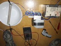
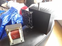
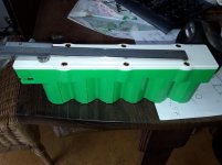
Recently i asked Doede ( DDDAC man) to make a kind of '' redesign '' of his 5/12 volt regulator board by removing the transformer, diodes and input capacitors because i wasnt planning to use them. This gave me a much small board which is easier to use.
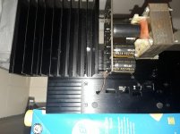
I have several '' spots '' where i will use it. Some will take more current like the Roon Nucleus so need to use a bigger heatsink.
As you can see the output cable from the circuit will be soldered on that board using a 5/6/7 cm cable ending with a plug that will be connected to the NUC power input.
I really think that this will be better than spending a few hundred Euro's on a separate DC supply in a slick box connected with a 50 cm cable ( which will have several '' interruptions '' if you start counting at circuit board in the slick box. We both start with a connection at the circuit board. Their second connection will be on the inside of the power output terminal. My second one will be on the plug entering the Nuc board.
I REALLY think that if you wanna take full advantage of very nice power supplies you must focus also on getting SHORT connections with very few interruptions.
Greetings, Eduard
P.s As you can see the DC input for the supply circuit board will have a short connection too. This is just a test set up to simulate the load with a big 200 watt resistor.
Recently i asked Doede ( DDDAC man) to make a kind of '' redesign '' of his 5/12 volt regulator board by removing the transformer, diodes and input capacitors because i wasnt planning to use them. This gave me a much small board which is easier to use.
I have several '' spots '' where i will use it. Some will take more current like the Roon Nucleus so need to use a bigger heatsink.
As you can see the output cable from the circuit will be soldered on that board using a 5/6/7 cm cable ending with a plug that will be connected to the NUC power input.
I really think that this will be better than spending a few hundred Euro's on a separate DC supply in a slick box connected with a 50 cm cable ( which will have several '' interruptions '' if you start counting at circuit board in the slick box. We both start with a connection at the circuit board. Their second connection will be on the inside of the power output terminal. My second one will be on the plug entering the Nuc board.
I REALLY think that if you wanna take full advantage of very nice power supplies you must focus also on getting SHORT connections with very few interruptions.
Greetings, Eduard
P.s As you can see the DC input for the supply circuit board will have a short connection too. This is just a test set up to simulate the load with a big 200 watt resistor.
Attachments
Thank you Andrea.
Of course Eduard, as short as possible.
But powering 2* DRIXO and 4*DBM require a minimum length.
I imagine two parallel cables for each clocks families, with 3 DC jacks in the two parallel lines.
You are free to comment this arrangement if I'm mistaking.
Of course Eduard, as short as possible.
But powering 2* DRIXO and 4*DBM require a minimum length.
I imagine two parallel cables for each clocks families, with 3 DC jacks in the two parallel lines.
You are free to comment this arrangement if I'm mistaking.
Hi,
May someone direct me towards the use of the PP micro board, please. Not sure I understand how to use it as it has a power input but also an Input/Gnd/Output classic 3 pins.
I believe it's from the previous power supply generation. I would like to know their use and how to plug them with the old Discroll board but also the new sin/square converter of the last generation as well as the new DiscrolL/Exo oscillators ? I bought 4 PP micro but also the big PP from the last gen in the same time !
Many thanks for your help/links
You can find infos about the PP-micro in post #136
The Well Regulated Power Supply
There are the BOMs for 15V and 3V3 output voltage.
TO supply the new DRIXO/EXO oscillators I suggest the TWRPS-pp, you can find the user manuals in post #208
The Well Regulated Power Supply
and the BOM in post #160
The Well Regulated Power Supply
The Well Regulated Power Supply
There are the BOMs for 15V and 3V3 output voltage.
TO supply the new DRIXO/EXO oscillators I suggest the TWRPS-pp, you can find the user manuals in post #208
The Well Regulated Power Supply
and the BOM in post #160
The Well Regulated Power Supply
If anybody needs a DST-5-36 I have bought a pair on ebay and only need one so I will gladly give one away at self-costs, PM me in case.
Greetings
Oli
Greetings
Oli
Thanks Andrea,
I have few questions about the PP-micro please before closing my BOM.
If I don't stack them on the former D&D board, can I use them for the 15V with a 17 to 18 V AC secondary or does it needs DC from J1 or the In vias either ?
Same question for the 3V3 : needs same 17V to 18 VAC trough J1 or Vin ?
About the shematic I see there is an optonal negative output I assume to use the PP micro as a standalone board or two for a +/Gnd/- supply: I swap the transistor 1 on the shematic by the one named 2 for a negative PP Micro ?
Now about the D&D : is there a big difference between the populated 3V3 & the 15V of the board VS the stacked PP-Micro, please ? If I stack them I don't populate the center of the D&D PS where the oap stands ? I talk in the context of AT Cut crystal only here with the old Discroll board only.
Sorry to bother with that.
Last edited:
TWRPS-pp micro needs DC input, while TWRPS-pp has rectifiers and filters on board.
For a negative pp micro you need:
- install Q101 and Q112 instead of Q1 and Q12
- reverse the polarity of all diodes
- reverse the polarity of all capacitors
- Q3 and Q5 are D44H11 instead of D45H11
- Q10 is D45H11 instead of D44H11
- Q4, Q6 and Q7 are BC860C instead of BC850C
- Q8 and Q9 are BC850C instead of BC860C
- Q2 and Q11 are 2SA1312 instead of 2SC3324
D&D board:
- Vo is the 15VDC output for the oscillators
- Vs is the 3.3VDC output for the squarer
Thanks
Thank you Andrea,
It's clearer. I assume J1 is for using PP-Micro elswhere than the D&D PS board with a non regulated Vdc then. Would a rectifier with CLC Pi filtering before can improve things more ? and then what Uh/ma chocks could you advise please ? (SMD?)
Is the D&D without two PP-Micro is good enough for feeding two Discroll first gen with AT-Cuts, please ? Or should I notice an hearing better difference stacking the further PP-Micro ?
Do you remember the range of Vdc it can handle max, and the minimum voltage more needed in relation to the output Vdc chosen - i.e. 3.3 V; 5 or 6 V ; 15 V ?
Is it a good idea, whatever we know LiFePo are not happy so much with regs, to use 2 in serie for the 3V3 or 5V output Bom to feed the PP-Micro? No danger for the reg and the load when the cells drops below the voltage needed ?
For the PP through holes, I believe a shematic for the sense and force outputs thingies would help to cable and should be included to the Pdf as you did for the D&D : it helps a lot the 101 electronic people as I am 😱.
As well as a shematic to use two boards if possible for a negative/Gnd/positive power supply.
Thanks again for your help.
Cheers
Last edited:
Yes, J1 is for external DC supply.
I believe a simple CRC filter is more than enough.
TWRPS-pp micro sould be better than the D&D on board regulators, but I have never compared them in a listening session.
About the Vdc to power the pp micro you can start from 7-10 Vdc higher than the regulated output voltage.
I wouldn't use anyway two pp micro in series.
I will update the TWRPS-pp and pp micro as soon as I find the time.
Many thanks Andrea, that helps. No urge for me for the pdf, it's more I think about others "electronic for dummies" as I am 😉
I was not talking about two PP-Micro in serie but using two A123 LiFePo in serie - so 6.4 to 6.6 Vdc - as voltage Dc for the PP - Micro for 3V3 or 6V output - LiFePo regs for the poors- : bad idea ?
I was not talking about two PP-Micro in serie but using two A123 LiFePo in serie - so 6.4 to 6.6 Vdc - as voltage Dc for the PP - Micro for 3V3 or 6V output - LiFePo regs for the poors- : bad idea ?
As I said you need at least 7Vdc higher than the output, so for 3V3 output you need at least 4 LiFePo batteries in series.
Hi,
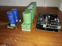
I have beginning to solder most of the resistors I have in the toolbox. The PP regulator is a pleasure to work with, precision of the diameter vias is superb.
I have seen some parts variation between the first and unique shematic and the official last BOM for the resistors and trim pot as some transistors, I think because 560BC are difficult to source, but the 2SK170BL are still.
So trim pot is not 1K anymore but 2K as some resistors have changed for few.
Is it due to the transistors changes ? In other words : if I have 550C/560C, I can not solder them anymore and must go for the 549C/559C with te last BOM parts values ??? For my limited understanding they are almost the same, just the 550/560 are a little better on the noise behavior !
2SK170BL : Where to source it in Europe please ? I know Banzai Music have them - as the 550/560C btw- but I don't know their origin and if this shop is serious, they are very sloooooooow ! Any other good local sources ?
Not subitual with care to the pins arrangement with BFA245A or easier to source J113 ?
thanks in advance
Edit :
@Andrea : the PP-Micro I will populate after the 3 PP throughole, is a beauty, It gave me the envy to try it with the TDA1541 VS the Pedja discrete very fast reg. I'm not sure here noise matters enough to choose on the noise behavior, but it worths a try 🙂 while caps matters a lot here as there are some mixed analog in the internal of the 3 the TDA1541A 3 voltages rails, but OT here.
As I'm building the two generation clocks at the same time, I think I will take perhaps one PP through hole and one PP-micro to feed two Discroll first gen as well 🙂 - and remain the D&D for another project -
Attachments
Last edited:
- Home
- Amplifiers
- Power Supplies
- The Well Regulated Power Supply