learn to hit the right buttons on your calculator......input 1.55 rms 2.19 p-p.....
1.55Vac sinewave = 4.38Vpp
The plan of the amplifier shows two resistors 15κ-10κ to give result 6Κ who in relation to the resistance value 330Ω give a gain value Χ 18,18 Resistance value 8,2K relation to the resistance value 330Ω give a gain value Χ 24,84 when i put 8,2k i get more wide square wave and the sound more clear/
Any advice please??
Have a look at my post #1776
Have a look at my post #1776
i think use 7.5K and 270R, gain ~ 30, it is good..
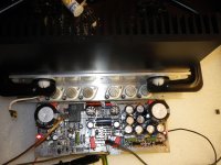
I have some illustrations complete amplifier, and amplifier measurements here:
http://www.diyaudio.com/forums/solid-state/208433-diy-gm-telos-amplifier-7.html
Last edited:
hi there, well done.....it looks great.
Apologies for asking, but do you have a final parts list for the build? I only ask as I bought the boards sometime ago, then suddenly there was alot of do's and do'nts, should be this this way/ or the other, so sadly I lost interest. Today I have log-in after quite some time and spotted your finished Amps..they look great. Cheers, Nicholas
Apologies for asking, but do you have a final parts list for the build? I only ask as I bought the boards sometime ago, then suddenly there was alot of do's and do'nts, should be this this way/ or the other, so sadly I lost interest. Today I have log-in after quite some time and spotted your finished Amps..they look great. Cheers, Nicholas
Vitalica:
Your build is greats!!!
What's the brand of toroid transformer? It's look very nice.
Your build is greats!!!
What's the brand of toroid transformer? It's look very nice.
Vitalica:
Your build is greats!!!
What's the brand of toroid transformer? It's look very nice.
TOROIDY.PL Transformatory Toroidalne Producent, Audio, Separacyjne, Trójfazowe, 230/110V, 110/230V, Na zamówienie
hi there, well done.....it looks great.
Apologies for asking, but do you have a final parts list for the build? I only ask as I bought the boards sometime ago, then suddenly there was alot of do's and do'nts, should be this this way/ or the other, so sadly I lost interest. Today I have log-in after quite some time and spotted your finished Amps..they look great. Cheers, Nicholas
Hi Nicholas,
I hope that is all the information here🙂
I'm on the board:
C3= 4,7PF
C5 = 10PF
C6 = 4,7PF
C7 = 4,7PF
T7 between B-C: 4,7PF
R20 = 330R (bias 100ma per transistor)
Transformers (TOROIDY.PL Transformatory Toroidalne Producent, Audio, Separacyjne, Trójfazowe, 230/110V, 110/230V, Na zamówienie) : 2x50V/500W (2 bridges for channel)
It is the same 2x50V /500mA for BD249/BD250
from the bottom PCB - 2x 10000/100V.
on PCB - 2x4700/100V.
Best regards.
Attachments
Last edited:
Hi vitalica,
There is a newer schematic, see blow
Somewhere between page 160-170, this new sch. surfaced. The thing I worried most is the T6 which has its CE 'reversed'. Worth discussion? I had a modified pcb laid for this new sch. too.
BP
There is a newer schematic, see blow
Somewhere between page 160-170, this new sch. surfaced. The thing I worried most is the T6 which has its CE 'reversed'. Worth discussion? I had a modified pcb laid for this new sch. too.
BP
Attachments
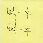
The thing I worried most is the T6 which has its CE 'reversed'. Worth discussion?
Why worry about it. There are many other things that are more critical and need attention (PCB track, actual measurement, component size and quality, etc). The amp is good but not because of T6. You can even use your favorite ccs if you have one.
I thought this one had been nailed a long time ago!
Both orientations result in a forward biased diode, so are equivlent.
The only difference, (not relevant here) is if the polarity is reversed; the top configuration sees a BE reverse zener of about 6.2V, the bottom one whatever VCBo is, which could be high.
Both orientations result in a forward biased diode, so are equivlent.
The only difference, (not relevant here) is if the polarity is reversed; the top configuration sees a BE reverse zener of about 6.2V, the bottom one whatever VCBo is, which could be high.
Attachments
Cliff,
what's wrong?
Your 896 by 896 pixel >100kB pic is perfectly visible/legible at the thumbnail resolution of 150 by 150 pixel and just 3.7kB
I do like your explanation of the difference in reverse orientation. 4 ways to connect and 4 different results.
what's wrong?
Your 896 by 896 pixel >100kB pic is perfectly visible/legible at the thumbnail resolution of 150 by 150 pixel and just 3.7kB
I do like your explanation of the difference in reverse orientation. 4 ways to connect and 4 different results.
Cliff,
what's wrong?
Your 896 by 896 pixel >100kB pic is perfectly visible/legible at the thumbnail resolution of 150 by 150 pixel and just 3.7kB
I do like your explanation of the difference in reverse orientation. 4 ways to connect and 4 different results.
I must be missing something?
Why is the resolution a problem for you? Are you still on dial-up 300baud? 😀
"4 ways ..." Not sure what you are getting at! I was trying to show that if the PCB had the transistor inverted it makes no difference since it is used as a forward diode in the CCS tail. So ONE result, not 4.
The reverse polarity version that you describe has either Zener type action, or Vcbo.
That is two different results.
That is two different results.
The reverse polarity version that you describe has either Zener type action, or Vcbo.
That is two different results.
Are you feeling grumpy this morning, Andrew? 😀
I mentioned the difference in Vz but pointed out that IN THIS CIRCUIT it is not an issue!
I didn't say it was an issue.
I noted your comments and the fact you were drawing our attention to how the device operates with different orientation and different polarity.
I had not thought that through, as thoroughly, as you have.
Although I didn't use the words. I was in effect thanking you for pointing out the 4 variations rather than just leaving us ignorant of the implications.
I'm still waiting for someone to post the PCB designs so that us TRUE DIYers can have a go at building the project.
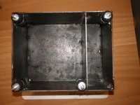
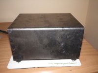
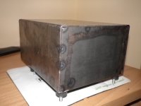
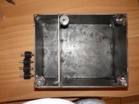
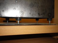
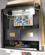
Golmund clone
Box-transformer
Box-transformer
Attachments
-
 IMGP0909-1.jpg887.4 KB · Views: 1,212
 -
 IMGP0915.jpg575.9 KB · Views: 293
 -
 IMGP0914-1.jpg677.8 KB · Views: 876
 -
 IMGP0913-1.jpg775.3 KB · Views: 987
 -
 IMGP0912-1.jpg544.7 KB · Views: 1,070
 -
 IMGP0907-1.jpg702.8 KB · Views: 484
 -
 013.jpg70.2 KB · Views: 577
 -
 IMGP0892-1.jpg673.2 KB · Views: 548
 -
 IMGP0893-1.jpg676.9 KB · Views: 411
Last edited:
χαλια ... χαλια ...χαλι μαυρο....
( that was cra**y work ... but in plain Greek )
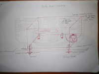
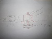
Nick the metal work is a masterpiece and i expect it when painted to look marvelous only i wonder how much of this tank made box will add anything to the sound of your amplifier ....
Your case ( and others also ) should be a subject to the NVA amplifiers article which in a few words said that steel boxes are no good for audio amps , aluminum boxes sound terrible , so they ended up with a plastic box but without screws since screws effect the sound of amp for the worst
Read the article ...it might change your aspect of life ....
( that was cra**y work ... but in plain Greek )
Nick the metal work is a masterpiece and i expect it when painted to look marvelous only i wonder how much of this tank made box will add anything to the sound of your amplifier ....
Your case ( and others also ) should be a subject to the NVA amplifiers article which in a few words said that steel boxes are no good for audio amps , aluminum boxes sound terrible , so they ended up with a plastic box but without screws since screws effect the sound of amp for the worst
Read the article ...it might change your aspect of life ....
as Nick is preparing to post the NVA article regarding the procedures and topology of the casing let me remind you that the Nva 80 is made around TIP 142 147 .....
If anyone else is interested in some more jokes ....please post here ...
Happy regards
sakis
If anyone else is interested in some more jokes ....please post here ...
Happy regards
sakis
- Home
- Amplifiers
- Solid State
- The Very Best Amplifier I Have Ever Heard!!!!