Does that amp schematic have enough parts. It will never be an Aleph!!!
Does all of that really improve the sonics? I am liking my Leach and this amp Alex and Nags are working on more and more.
Tad
Does all of that really improve the sonics? I am liking my Leach and this amp Alex and Nags are working on more and more.
Tad
The Goldmund Gold Cubes are part of the Mimesis series. They use 100% identical schematic to what I posted, but only with 2 pairs of MOSFETS instead of 3 pairs.
Alex, as always you're doing an amazing job and I cannot wait to see your final PCB. If I may make a quick suggestion and maybe someone else can also discuss weather it makes sense, or not... Can you leave the 24V relay on the main circuit board? Sonically this should be better, as the output signal will travel through the relay and to the speaker terminals, staying on the same PCB. If you mount the relay on the separate PCB, then the output signal will have to first travel to the protection circuit PCB, then back to the main PCB before it goes to the speaker terminals. Thanks!
Can someone confirm if this amplifier would be stable below 4 ohms? it does not appear so to me, with such a small power supply and minimal outputs ...
It's extremely stable below 4 ohms. Just like any other very high quality amplifier. Here are the specs, at the bottom under "Mimesis 9.2 Technical Data." This is the same exact amplifier which schematic I posted on page one.
http://velero-ii.com/Kraftwerk_Audio/Goldmund_Mimesis_9_Amp/Goldmund_Mimesis_9_Amp_Brochure.pdf
http://velero-ii.com/Kraftwerk_Audio/Goldmund_Mimesis_9_Amp/Goldmund_Mimesis_9_Amp_Brochure.pdf
In reply to your answer your question in Post #304:
I have obtained the best results by combining all the stuff: PSU - AMP - LS Protect - on the same PCB.
The girlie's sticker need not be there, though.
Best regards - Rudi_Ratlos
An externally hosted image should be here but it was not working when we last tested it.
I have obtained the best results by combining all the stuff: PSU - AMP - LS Protect - on the same PCB.
The girlie's sticker need not be there, though.
Best regards - Rudi_Ratlos
Last edited:
PCB
Thank you for the pictures of the module NagysAudio.
I have found a picture on the net of the acual Memesis 9.2 monoblock.
On the left is the protection circutry and above the power caps is the fuses, I think they was 8A fast types.
One thing NagysAudio, do you have access to a Memesis board from this time 1980 - 1990?, some photos? I am wondering how the ferrites was mounted (if any) with the TO-3 cased power transistors.
One other thing, looking at the PCBs on the Memesis 9.x photos they are manufactured with tin coating on top of the copper traces, sometimes called HASL. This is the old fachion way of making PCBs and I really like that. This may be one reason why the old version did sound better than the current models. The current models seems to all have green solder masks. I think that the green film, solder mask, can have uncontrolled effects of the performance of the circutry. I have not found any discussion about this in the forum so here is a link that explains it: Article - RF PCB Design (see third section)
The board is not going to be wave soldered anyhow so why not try HASL for this project? I have seen some other very expencive audio equipment using immerson gold instead of solder masks...
Hope this helps
Attachments

tommy1000 - Yup! That's the picture of Mimesis 9.2, the schematic that I posted! The fuses are actually 10A fast types. The amp has a super simple power supply, 2 transformers and a bridge, all potted of course because they're Goldmund! The TO-3 MOSFETS did not have ferrite beads on them! I have a Mimesis 6 amplifier and a Mimesis 3 amplifier, but I rather not take them appart to take pictures. Many can be found on the web, like the one you just posted.
I agree with you on everything you said regarding the PCB. So then here's the question for the forum... Does anyone have the ability to make a PCB board in this fashion?
I agree with you on everything you said regarding the PCB. So then here's the question for the forum... Does anyone have the ability to make a PCB board in this fashion?
Last edited:
Yes.
It would finally look like this one, have the same "touch and feel":
But you have to do the prototyping first.
Best regards - Rudi_Ratlos
An externally hosted image should be here but it was not working when we last tested it.
It would finally look like this one, have the same "touch and feel":
An externally hosted image should be here but it was not working when we last tested it.
But you have to do the prototyping first.
Best regards - Rudi_Ratlos
Last edited:
I'm in too, for 2 pairs of the board, plus 2 pairs of the protection circuit boards. How much approximately would these particular boards cost?
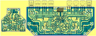
PCB final version .....
.... after countles variant and revisions the final PCB 🙂
Regards Alex.
.... after countles variant and revisions the final PCB 🙂
An externally hosted image should be here but it was not working when we last tested it.
.Protection board on top of main board .Regards Alex.
Attachments
Last edited:
Is a hole needed in the protection board to access the pot on the main board?
IMHO I think the rails need to be larger.
An Excellent job of layout ALEX Excellent...
IMHO I think the rails need to be larger.
An Excellent job of layout ALEX Excellent...

Hello
I have a few question .
These amp would work properly with the old PC board ?
If yes , can I use any another type protection? These amp would work with out protection properly??
Of course is good to have protection to save my speaker in case something goes wrong..
Nagy please let me know..
I have already a great speaker protection from Quasi . I made several PC boards and it work with 24V. The regulated power sup. built on the PC board..
It use different type of relay (Omron).
When it sense more than 0,5V offset automatically disconnect the speaker from the amp
Greetings
Gabor
I understand that this is not a nice question to ask on this thread. Nevertheless, is it possible to use anyone of these JFETs instead of 2N5565: 2SK170, 2SK246 or BF862? Thanks.
- Home
- Amplifiers
- Solid State
- The Very Best Amplifier I Have Ever Heard!!!!