
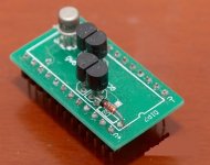

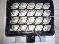
tommy1000 - A2 module is identical to the older A1 module. The only difference is that Goldmund uses surface mount resistors on the A2, they're on the bottom of the board, you can't see them in the picture. While the A1 module is all point to point soldered, no circuit board inside. I took apart both modules, I can post a picture of the A1's internals if anyone's interested.
Goldmund still uses till this day the same exact schematic. Even in their $100,000+ components. Of course they have different chassis, more complex power supplies as the price goes up, better mechanical grounding and thermal grounding, digital controls, more pairs of MOSFETS in the more powerful amplifiers, but the fundamental schematic remains the same.
These amplifiers sound incredible. I chose to post the older Mimesis amplifier's schematic because they're easier to build. They use a very generic power supply, transformers (X2)/diode bridge, no digital power ons with delay, etc.
And the funny thing is this: The old Mimesis amplifiers sound better than even the most expensive ones from Goldmund today. That's why it's important to use the exact parts from the older Mimesis schematic, especially since all the parts are readily available online as NOS from eBay, Newark, Mouser, Farnell, Digikey, etc.
Last edited:
Nags,
I would appreciate a nice close up of the A1 module you so nicely chose to offer.
I wonder since the frontend sections of all the Goldmund are essentially the same why the slew rate and some other specs are WAY up there on the Telos units.
Would not a dual jfet be a better choice for the discrete OP amp than two separate jfets. It should not change anything except the matching accuracy and thermal drift. w
And what are the thermal characteristics of the 3M electrical insulating epoxies used for potting components. I was not able to find that data.
Have we gotten any closer to being able to construct one of these.
Tad
tryonziess - I have built and sold 2 of these amplifiers. Both with cheap circuit boards, nowhere near what Alex has created. I also personally own Goldmund Mimesis 3 and Mimesis 6 amplifiers.
I will post a picture tonight, when I get home from the office of the A1 module.
You're absolutely right!! Dual jfets are SIGNIFICANTLY better, that's why Goldmund uses them and it's also in the schematic I posted. Please take a more careful look, the 2N5565 is a dual jfet. You can also see it in the picture that tommy1000 posted.
As for thermal characteristics of the glue, I have no idea. It's extremely hard brittle glue. It was a pain trying to take one of those modules apart. I had to heat it up with a small torch. Once heated, it would become soft and grainy for a few seconds and I was able to cut piece by piece at a time. Then I would have to reheat it again. Extremely time consuming.
Would not a dual jfet be a better choice for the discrete OP amp than two separate jfets.
A DIP8 NPD556* is significantly better than a TO71 2N556*.
A-Because the NPD are monolithic dual JFETs, the 2N5564/5/6 are two JFETs in a can.
B-Because plastic is better than metal hats. Don't trust me, ask the RF-headrooms Phred and/or Jocko on the beach.
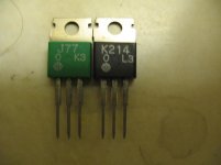
Gaborbela; your K1058 is really a fake one. Get some from different source(15 years ago) and nothing look like this.
Hello
I'm very happy with those fake mosfets.😀
They sound better than the original Renesans!! Thank God!
I meet several Hitachi device marked white , even black on the green plastic case.
I do not want to argue over these! I have no time for that.😀
I know what I purchased ,I have laser marked Hitachi , Renesans . These was tested and com pared with them!
I do not feel I have to prove the originality to anyone!!!!
But I like people who think because they never sow something that not exist or fake!!
Please do not take it personally!
Some more fake Hitachi.🙂
Attachments
Last edited:
False Gods!
The notion that these amplifiers are increadible is false. They are good amplifiers but on the verge of instability... so beware of the load and speaker cables you use. The circuit can be improved quite a bit and is worth building but in it's present form it is almost straight out of Hitachi's data book with a few improvements, nothing groundbreaking or new.
It is well worth the build with the excellent pcb design proposed, but there is more to be learned by improving it, so often we come to incorrect conclusions about an amplifiers sound after gazing upon an expensive chassis (which is excellent in this case). I wonder how much better it could it have been if some of the chassis budget could have been spent on an improved design. All that glitters is not gold but maybe it is in the eyes of the beholder.
.....by the way I am no big fan of the dc to light ideal.....it is fraught with perils such as blown speakers and the loss of the blue smoke that power these devices.
Jam
Attachments

Last edited:
I think most of these companies purposefully build inferior designs so they have room to upgrade.
I think most of these companies purposefully build inferior designs so they have room to upgrade.
This can be good for us in the DIY world - we do not have constraints of meeting market demand or profit ratios dictated by the accountants and share holders. 😀
The notion that these amplifiers are increadible is false. They are good amplifiers but on the verge of instability... so beware of the load and speaker cables you use. The circuit can be improved quite a bit and is worth building but in it's present form it is almost straight out of Hitachi's data book with a few improvements, nothing groundbreaking or new.
Jam
Exactly what I tried to state to the followers of "false gods". The input stage with J201 FET's I have "built to death". The VAS is quite substandard. Even with MPSA92/42's , a Symasym or otala style VAS would be quite an improvement. the original hitachi design would even be preferable over this one. The percieved better sound by undercompensating this particular design is unwarrented to achieve increased fidelity. It is all in the loop gain vs. compensation scheme used that determines the resulting sound.
Reliability need not be cast aside to achieve the best sound in a substandard design.... redesign it , or at least simulate it as it is , find out it's high order harmonic structure .. THEN redesign it with reliability in mind.
OS
Yeah I can't imagine anyone saying improvements to the circuit would have a negative quality on sound...just doesn't make any sense really.
gaborbela - Can I ask you where you got the schematic from? This looks partially like their late 90s early 00s JOB based circuit amplifiers mixed with Mimesis input stage. I will double check and get back. From the looks of it, I will say this is a fake NOT Goldmund schematic. Some sort of a clone/copy, but from someone who did not have the JOB's input stage schematic, so they used A1 block from Mimesis instead. Probably using the A1's schematic from my previous posts on the internet.
Hello
One of the main reason I avoided these clone these PC board use SM resistors to!
Here are some info , I forget to delete from my e-mail.
The rest I deleted , pictures etc.
From: watchara saladkaew <scalaudio@hotmail.com>
Subject: Goldmund
To: mathszlo2@yahoo.ca
Received: Thursday, July 29, 2010, 11:25 PM
Hi gabor
I just received your request from Mr.Anadigit
My goldmund Mimesis29 clone is used original parts and well matched.
200WRMS with +/-70V supply rails. 400WRMS into 4 Ohms
Minimum load are 2 Ohms into 700WRMS
Thanks
Watchara
I deleted some parts of both email address but if someone interested on that clone you can ask for the email address.
He wrote he has Gamut kit also , and more expensive higher power Goldmund XLR input - output....
But please I have nothing to do with these amp or with the guy , no financial interest!
Greetings gabor
Last edited:
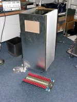
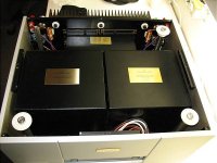
Some detailed info from the Goldmund 29M .
GOLDMUND MIMESIS 29 et 29M
The pictures I received from Mr. Wathara similar like these but that was the mono block verizon!
That had only one transformer , at least had one transformer cover.
Gabor
GOLDMUND MIMESIS 29 et 29M
The pictures I received from Mr. Wathara similar like these but that was the mono block verizon!
That had only one transformer , at least had one transformer cover.
Gabor
Attachments
Last edited:
You never sow God neither anyone of us , actually only Jesus sow him .
Still exist and not fake!
Greetings
Still exist and not fake!
Greetings
But I like people who think because they never sow something that not exist or fake!!
I made a mistake in that sentence
What I wanted to write
I'd like people who think that way!!!!
Because they newer sow something like that that not exist or right away fake!!
There are lot of them..
But if it makes you happy please write what ever you think .Or think what ever you want!
I'm not upset , I know the device , it was tested thoroughly , sound wise etc!
Tomorrow I will buy more , actually I need one more 2SJ162 to have all the matched pairs I have a need
Also my fried use it in a Class A amp 20 or 22 rail voltage 1.2A...Just sound fantastic, even tube amp fanatics agree on that.
Greetings🙂
You never sow God neither anyone of us , actually only Jesus sow him .
Still exist and not fake!
Greetings
Here the real one you need............but you prefer fake *made in Japan*
Attachments
- Home
- Amplifiers
- Solid State
- The Very Best Amplifier I Have Ever Heard!!!!