ThanksMr Nguyen seems to have good resources.
Can you show more pictures? I have resources very reliable but i am not see the actual pictures.😕
A stereo amplifier with dual polarity supply rails could have 4 sets of smoothing capacitors, if each amplifier has a separate PSU.
6 paralleled 8m2F would give +-49m2F per channel, resulting in 196m8F. Or as the brochure says approaching 0.2F
Exactly it is 72x100uF = 7.200uF( one mosfet one capacitor) + 4x1.000uF = 11.200uF for output stage(all)
Not included capacitor for Vas,pre,...
If they combined all the capacitors in a machine, I have no idea
Last edited:
Hien,
72><24.
That should alert you that, you have misunderstood something about the data you are reading.
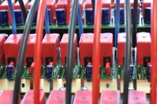
The 72 caps next to the 72 output devices are the decoupling caps. The 100uF quoted also confirms they are likely to be decoupling caps.
The 24 caps are in the power supply.
72><24.
That should alert you that, you have misunderstood something about the data you are reading.
The 72 caps next to the 72 output devices are the decoupling caps. The 100uF quoted also confirms they are likely to be decoupling caps.
The 24 caps are in the power supply.
No,in main power supply have not caps,only diode rectifier.Hien,
...
The 24 caps are in the power supply.
The 4 capacitor of soft star
regrards
Attachments
Last edited:
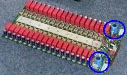
72x100uF = 7.200uF( one mosfet one capacitor) + 4x1.000uF = 11.200uFWhat is post1835 pointing to?
Place me bold on the top
it is in the blue box here pictures
Attachments
Last edited:
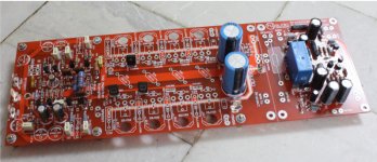
Yes,it is connections to power supplyWhat is this part/function of the PCB? Seems to be many of them. Connections to power supply?
Attachments
Are they connected directly to the rectifliers?
Yes,is it.
On board main power supply has large pads, wires will be soldered to it and bundled to the output board.
Attachments

Last edited:
What is the function of the other PCB that sits above the power supply board? Can you show me?
🙂...What is this part/function of the PCB? Seems to be many of them. Connections to power supply?
Attachments
Wow, look what turns up!! Any more pictures?
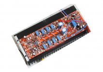
Hi tommy1000!
This my Clone Amli!
Thanks
Attachments
Last edited:
And!
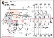
I use this circuit!
thanks
Have a few problem in circuit.
1. I drew the wrong and that you was copy the wrong to your circuit (see picture)
2. MPSA42/92 not be used with +/-75V in the Vas .
3. Current of Vas the same as your circuit is (2.4/257.5)/2 = 4.66mA not 6mA you wrote in circuit.
Attachments

Have a few problem in circuit.
No wrong, and no copy of you!
I practiced many times, to have the same value!
Schematic you gave false and not true reality!
The values given are based on my practice many times, finishing last, but maybe it is just the beginning of the capacity.
Last edited:
I said I drew the wrong, if you draw like me, you also wrong!
Right the same as normal, but wrong the same as is sure to copy.
In here,many people have good knowledge,they will see now.
Right the same as normal, but wrong the same as is sure to copy.
In here,many people have good knowledge,they will see now.
Last edited:
quanghao said:No wrong, and no copy of you!
I practiced many times, to have the same value!
Schematic you gave false and not true reality!
The values given are based on my practice many times, finishing last, but maybe it is just the beginning of the capacity.
You have no knowledge of electronics so your practice does not mean.
If you have knowledge of electronics,you did not draw like that(you say your circuit is right).😉
Have a few problem in circuit.
1. I drew the wrong and that you was copy the wrong to your circuit (see picture)
2. MPSA42/92 not be used with +/-75V in the Vas .
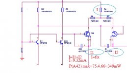
Please see the image, line I is fixed. I = I1 + I2, I1 I2 increases, the reduction should decrease the VCE.
VCE Q29 is inversely proportional to I2 so P = I2.75 = 4.66x75 = 349mW <625mW.
What do you think it??
Attachments
- Home
- Amplifiers
- Solid State
- The Very Best Amplifier I Have Ever Heard!!!!