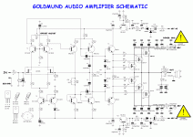
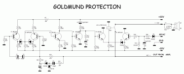
Temp sensing
NagysAudio, is seems there is a temperture sensing device (NTC) mounted on the heatsink in the pictures of the 9.x amp. Can you check the schematic you have been sketching from to see if there is somthing more missing?
NagysAudio, is seems there is a temperture sensing device (NTC) mounted on the heatsink in the pictures of the 9.x amp. Can you check the schematic you have been sketching from to see if there is somthing more missing?
I have made that one a long time ago, I serviced it and still have it. Its JLH's lateral MOS. Very nice.
Where would you rank it on your amp list?
Last edited:
Hey
its funny, but I just found that I have a pair exact like those very first and original C50 / K135
and they are from a JHL I build many many years ago
but from his very first and simpler schematic
unstable, and I probably only have them because they had burned and been replaced
I heard it burned again, some time after I sold it
but it sure sounded very nice while it lasted
sorry if it sounds slightly sarchastic, I didnt mean to
Oh, in that case : CJ Evolution2000
=> http://img301.imageshack.us/img301/5122/ev2000ouvertbiaisfacedroitelq3.jpg
(also Hitachi MOSFETs, 5 pairs for 200W)
Do you have a schematic?
I notice the valve in the window.
I would absolutely laugh my head of if it was a copy of my bass amp.
thanh,
We were just kidding. You have a legimate question and Goldmund has sometimes (well many times) been sketchy about their specs.
That's the Shadow, a character from a comic book.
Time for a cold Foster's now.
G'day.
Jam
We were just kidding. You have a legimate question and Goldmund has sometimes (well many times) been sketchy about their specs.
That's the Shadow, a character from a comic book.
Time for a cold Foster's now.
G'day.
Jam
Last edited:
tommy1000 - Nothing is missing from the original Goldmund schematic. I've seen some Goldmund amps with the heat sensing device and some without. The schematic that I have is without. This is something that would have to be decided on by each individual builder, if they want to include it, or not.
Salas,
Built that one too.....a great amplifier. JLH knew his stuff. There were rumors of a higher powered version but I never came across the schematics.
Jam
Built that one too.....a great amplifier. JLH knew his stuff. There were rumors of a higher powered version but I never came across the schematics.
Jam
Last edited:
I think it would be a good idea if we started up a new thread where we could post as many schematics as we can find that use lateral mosfets.
Then we could rate them.
Even better would be to choose the best one and then go "anal" with it as someone said earlier.
I like wide bandwidth, but I don't like output inductor coils to keep the amp stable.
Then we could rate them.
Even better would be to choose the best one and then go "anal" with it as someone said earlier.
I like wide bandwidth, but I don't like output inductor coils to keep the amp stable.
Where would you rank it on your amp list?
Behind PP triode tube amp for expression and 3D, ahead of many BJT and chip amps for tone and body. Runs at 100mA bias 0Tc and have never blown a Mosfet since 1987.
Salas,
Built that one too.....a great amplifier. JLH knew his stuff. There were rumors of a higher powered version but I never came across the schematics.
Jam
He was just advising a 2nd pair of outputs and +/- 80V plus double the filter capacitance and more Tx VA.
I think it would be a good idea if we started up a new thread where we could post as many schematics as we can find that use lateral mosfets.
Then we could rate them.
Even better would be to choose the best one and then go "anal" with it as someone said earlier.
I like wide bandwidth, but I don't like output inductor coils to keep the amp stable.
Good idea is to start new forum for 'Goldmund' clones.
I started new thread: http://www.diyaudio.com/forums/solid-state/175192-mosfet-bjt-quasi-amplifier-protect.html with 'Zeck' amp, use HITACHI laterals mosfets and MOTOROLA bjts in output stage.
QUOTE=NagysAudio
T6(BC182B) is connected wrong/reversed. D1(ZD6V) should connect to the Collector. R12(33K) should connect to the Emitter.
hello.
........i think there is a difference between schematic post 1 and the actual schematic..........perhaps somebody should have a look at this.
greetings
T6(BC182B) is connected wrong/reversed. D1(ZD6V) should connect to the Collector. R12(33K) should connect to the Emitter.
hello.
........i think there is a difference between schematic post 1 and the actual schematic..........perhaps somebody should have a look at this.
greetings
Good idea is to start new forum for 'Goldmund' clones.
might be a good idea
but still, you critical guys around here could be the sole reason the boards are still not yet in production
which at this point is a positive thing, or it would have had many errors
worth to think about
as I said early on, dont rush it, take your time, please
Revised again .....schematic and pcb ..
.....I have made correction in schematic and PCB , now it seams to be correct .
Alex.🙂
.....I have made correction in schematic and PCB , now it seams to be correct .
Alex.🙂
Attachments
Nags,
would you be kind enough to put together a BOM for the finished design when it is approved.
I would like to get my parts sorted out.
Tad
would you be kind enough to put together a BOM for the finished design when it is approved.
I would like to get my parts sorted out.
Tad
- Home
- Amplifiers
- Solid State
- The Very Best Amplifier I Have Ever Heard!!!!


