Wahab,
I just think you proved my point, you have limited the bandwidth of your amp. Try driving the amp with a square wave into 8ohms in parallel with 2uF and you will see what I mean.
My criteria for a good design is to apply minimum compensation to a completed design to achive your goal rather than applying a lot of compensation to an oscillator to achive the same ideal. Which is the better approach?
Jam
My criteria for a good design is to apply minimum compensation to a completed design to achive your goal rather than applying a lot of compensation to an oscillator to achive the same ideal. Which is the better approach?
Jam
True that personnaly, i did follow the first path, that is,
autocompensated circuit, i.e, no external compensation caps at
all, the only ones being those intrinsical to the components.
Not sure that this is the best for hifi since it was designed
as a concert stage monitoring amp....
the MOSFETS were point to point wired.
With Lateral MOSFETs, how adventurous.
Hi Alex,
Schematic :
should it be C/T3-->B/T7 ; C/T4-->B/T8 ???
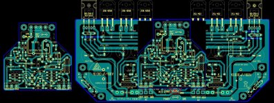
pcb :
if you can make a projection from the daughter board (as in red lines) with a M3 hole you can have a mechanical support for the DB (it is tripod now) Just make sure it align with the M3 hole (which you have to add) on the mother board (centre of your signal ground ) .
In post#261 there are 2 pairs of thermal coupled to-92, would that be BC546+546 ; BC182+182. If it is then if you swap your 2 BC182 (and some associate components) we may make them coupled as in Post#261. But for the BC546, we might have to wait for a double side pcb.
Starting to worried about the L1. With a limited spaced like what we have, we might have a hard time implementing it. I have done something like 1.2mm wire, 1cm core dia., 15 turns, pitch (~coil length)= ~20mm. Wonder if a 22T coil can fit into there.
Schematic :
should it be C/T3-->B/T7 ; C/T4-->B/T8 ???
pcb :
if you can make a projection from the daughter board (as in red lines) with a M3 hole you can have a mechanical support for the DB (it is tripod now) Just make sure it align with the M3 hole (which you have to add) on the mother board (centre of your signal ground ) .
In post#261 there are 2 pairs of thermal coupled to-92, would that be BC546+546 ; BC182+182. If it is then if you swap your 2 BC182 (and some associate components) we may make them coupled as in Post#261. But for the BC546, we might have to wait for a double side pcb.
Starting to worried about the L1. With a limited spaced like what we have, we might have a hard time implementing it. I have done something like 1.2mm wire, 1cm core dia., 15 turns, pitch (~coil length)= ~20mm. Wonder if a 22T coil can fit into there.
Attachments
I see...you may be right Jay..it is possible..for sure it is
I will not assemble to check, as i have lots of things already planned to do, and satisfied with my own "best wide world amplifier"..but i think this may be interesting and i hope some folks decide to build it to inform us the way it sounds when compared to others "best wide world amplifiers"....gladly we have a lot of best ones.
hehehehehe...this is good!.... this is the spirit, the joy and the fun!
regards,
Carlos
If anyone's interested I will start a new thread to discuss improvements and mods to this amp, including if needed stability as Jam describes. I know of one (pointed out before) that brings THD down to .0026% at full power into 4ohms at 1KHz, and actually improves phase margin (simulated) by 10 degrees.
- keantoken
- keantoken
Keantoken,
I think that is a great idea. OS has done much work on this topology and and with your input we should come up with something great.
Regards,
Jam
I think that is a great idea. OS has done much work on this topology and and with your input we should come up with something great.
Regards,
Jam
There are no SPICE models for the BSS71/74, and I didn't find any datasheets with the necessary curves to create a proper model from scratch. However in hindsight I think the 2N5551/5401 are a much better substitution (ducks) than the 20W japanese drivers.
I believe that the 2N5551/5401 would be a better replacement had the supply rail is not as high as 80V 🙁
The 5551/5401 has Vceo=150V while BSS71/74 has Vceo=200V. Lowering the rail for the driver will decrease the slew rate I believe, so I wont go for lower rail. Instead I will use Toshiba C3298/A1306 100M 200V driver. But the rail voltage will be slightly lower as I will use 55Vac instead of 60Vac. But then that is 77Vac before the regulator, which means I may still be able to use 2N5551/5401... What kind of risk would it be? 😕
I will not assemble to check, as i have lots of things already planned to do, and satisfied with my own "best wide world amplifier"..but i think this may be interesting and i hope some folks decide to build it to inform us the way it sounds when compared to others "best wide world amplifiers"....gladly we have a lot of best ones.
And what is your "best amplifier" Carlos? Do you dare to say that your DX amp is better than AKSA? 😀
It is difficult to compare my amps with yours because we have different taste. If at least you like mosfet amps may be we can do some "comparison" 😉
I prefer mosfet so my bipolar amp projects is running very slow. Mostly I just trying to get the best from transistors I have at hand. Since I have plenty of BJT-N, especially old 2N773, I try to find the best quasi amplifier in class-B. Currently I use Quad 303.
You see, even in bipolar term we have different taste. Your taste doesn't match with your age I would say. Your wife must be a very understanding woman isn't she? 😉
WHat is the frequency response of this amplifier?
Is it higher than F5?
I personally think one of Erno Borbely designs might be better than this, but what do other people think?
Having said that, the topology of this amp is very similar to my favourite bass amp of all time. However most of the magic was in the valve preamp stage.
But even still even without running the valve stage the amp was/is the best amp I have heard (according to my tastes).
What about this one? (see image)
Attachments

What is the frequency response of this amplifier? Is it higher than F5?
Very amusing post.
I know I am a funny guy, but I would still like an answer.
Maybe I should do the math, but there seems to be some disagreement about the slew rate.
My point is F5 is quite high bandwidth without any output inductor or compensation to keep it stable. On top of that there are no capacitors at all in the circuit.
Where as, this circuit seems to be held together by compensation caps etc to try and keep it under control.
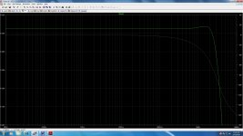
Just for people who have not been acquainted with F5, here is the frequency response.
Attachments
Last edited:
My point is F5 is quite high bandwidth without any output inductor or compensation to keep it stable. On top of that there are no capacitors at all in the circuit.
Where as, this circuit seems to be held together by compensation caps etc to try and keep it under control.
F5 is using VFET which has higher transconductance than LFET. It is not easy to design a fast amp with LFET, so compensation is necessary. Even in many similar two-stage designs, LFET has similar problem.
VFET is quite unusable in class-B amps like the Goldmund. And more importantly, how much wattage will you expect from F5 or other class-A amps? Whatever your speaker is, you may miss quite a lot of music using such a small amplifier, imho.
BTW, while we are in the Goldmund thread, just a guess, I believe I would prefer an Aleph with P-channel VFET (IRF9240) and 2N5565 JFET input stage than the F5. But the power supply must be made quiet (using L). In balanced mode if necessary. Measurement will be still worse than F5 but musicality and importantly the power will be better I guess.
Basically, you were comparing an orange (F5) with an apple (Goldmund) there...
You can easily scale F5 to 100W, maybe not all in Class A, but you don't need 100W class A. You could go 50W class A and the next 50 in class B.
Or you could just go 100W class A if you had the necessary heatsinking.
The other option would to build a balanced version like Patrick and a few others have done.
I am not saying the F5 is better, but there seems to be a lot of emphasis around the specs of this goldmund amp as if this is the secret to it's high performance, when there are other amps with just as impressive specs which are even easier to build.
Last edited:
thanh,
..................only the Shadow knows. 😀
Sorry jacco made me do it.
Jam
I don't know if you guys are laughing with me or at me.
Never mind I don't care. I love everyone here.
Who is the Shadow?
Is this it?
http://en.wikipedia.org/wiki/The_Shadow
Last edited:
- Home
- Amplifiers
- Solid State
- The Very Best Amplifier I Have Ever Heard!!!!