I would not say anything without listen first...well.... people is different.... i have enormous respect by the reality...and very low respect about theories and suppositions....but people goes travelling in this long horizontal cursor..from the rigth to left....i am half way in the reality side...... ahahahahahah!... i think so....who knows.
I have build so special things...so nice and theorically perfect, made by wise and skilled guys and gave a shot on the board so awfull result the sound reproduction.... that i would not be surprised if this one is really "the best wide world amplifier" or the "worst lemmon on earth"
Carlos, I think I know your preference. If you want to know the real sound of the schematic you should listen to the original Goldmund or at least build this circuit with original parts.
If you build it the way I want to prototype it, I strongly believe you will not like it. Surely it is not "the best amplifier" even if you use the original parts. But for me, I think I have a feeling about the sound of this schematic, and that I will like it (even if it is not really a "clone" or duplicate). First, because I'm familiar with the output stage and it's driver. Second, because I think I have something in common with the designers and may be I know how they came up with this topology. There were many out there, there's nothing to stop them from choosing other topologies. With such a high price for the product, what they need to know is how to choose a good sounding one and how to make it better sounding through implementation.
If you believe that "there's no best amplifier" then you have to believe that there are the subjective preferences and the typical sounds of amplifiers. You just need to know what your preference is.
And you have experience building an amplifier in the proximity of oscillation state...
.... the schematic was made , if some error are found , please let me know to correct schematic and post it again .🙂
Alex.
Look at the emiter of Q12
Attachments

SIMULATION TIME
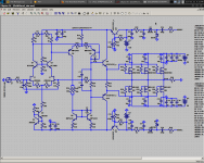
I'm going to simulate this. I SOMEHOW, it was fate I guess, managed to get the 1058/162 models working.
I am still working with the simulation, and will post what I have when I'm finished.
First, since there are no BSX71/74 or BD249C/250C models, I substituted the 2SC4793/A1837. For the BC182B, I substituted 2N5550 which seemed similar enough. I was lucky to have models for the input FETs, though I can't say if they're any good. If you know of any better substitutions and have models for them, please post.
What should the bias be for the outputs? Simulation currently shows 300mA/device, is this normal?
- keantoken
keantoken - The original transistors are BSS71/BSS74, NOT BSX71/BSX74. If you're ging to substitute all of these parts, then what's the point of the simulation really? Especially the input stage's dual jfets, 2N5565s. Just saying...
Last edited:
Simulation can only tell you basic things about how a circuit will sound, and it's been stated repeatedly that the circuit should be built exactly as the schematic. Even if we had all the right models, most of them probably wouldn't be very accurate except for basic behavior. Even the MOSFET models themselves cannot model crossover right.
So, it is almost a lost cause. But I did read someone a few pages back wanting a simulation so they could see the operating points. Simulation helps with basic design and knowing whether or not the circuit is operating normally.
I also wanted to mess with an FET amp.
- keantoken
So, it is almost a lost cause. But I did read someone a few pages back wanting a simulation so they could see the operating points. Simulation helps with basic design and knowing whether or not the circuit is operating normally.
I also wanted to mess with an FET amp.
- keantoken
About FET models... I'm dumb with FETs, dunno if the ones used are lateral or vertical (whatever that means), but for vertical MOSFETs, we are only recently able to model them correctly. Here is a link for anyone who has joined the LTSpice Yahoo group:
Yahoo! Groups
LTSpice now supports a few new parameters, although no doubt we must wait for some zen SPICE hermit to jig them into the existing SPICE models.
- keantoken
Yahoo! Groups
LTSpice now supports a few new parameters, although no doubt we must wait for some zen SPICE hermit to jig them into the existing SPICE models.
- keantoken
If you can please use as many original transistors as possible, I would be interested in seeing your simulation 🙂
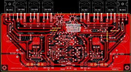
Ok everyone... Alex's PCBs look terrific in post #377. Alex, can you please post the printable .pdf files of these boards? I checked them over and don't see any mistakes. I also can't think of anything to change/recommend. Can you guys also check them over to see if you can find anything wrong? Please compare it with my original Goldmund schematic that I posted on page one. And also, any last minute changes/requests?
If everything looks good, lets move on with the group buy. Who is willing to organize this and take everyone's order?
Rudi_Ratlos might be able to organize one via PCBCART who would supply the requested and superior Electroless Nickel boards.
bigpanda can also supply the boards. Not sure about the Electroless Nickel boards.
A rough estimate of the pricing is approximately $25-$30 for a pair of these boards.
Please correct me if I'm wrong on anything and please share your thoughts.
How about a VOTE
New threads called
HITACHI Improved Design = HID
'Goldmund' is just another HITACHI based amplifier, no need for new threads, there is already threads for similar designs.
Hi,
But I called GM-CLONED for this model since 2007 !
I search for hard to obtain vishay draloric smd resistors and original parts 2 years ago and now very happy with them.
My friend used it and modified to balanced version in a name of LETOS (twisted words) model.
Thanks
Anadigit
Hello Nagy
Do these amp how is in these PC board would work?
Please let me know.
It is confusing because first was these now it became something total different (at least to me)
At first I would test these if work , less cost , less parts etc .
OK you heard the amp but different people with different taste.
To you may me something the World best and to me or others probably something else.
Al I want to know if I power up these do these work??
Thank you
Greetings
Attachments
Simulation can only tell you basic things about how a circuit will sound, and it's been stated repeatedly that the circuit should be built exactly as the schematic. Even if we had all the right models, most of them probably wouldn't be very accurate except for basic behavior. Even the MOSFET models themselves cannot model crossover right.
So, it is almost a lost cause. But I did read someone a few pages back wanting a simulation so they could see the operating points. Simulation helps with basic design and knowing whether or not the circuit is operating normally.
I also wanted to mess with an FET amp.
- keantoken
Yes, Keantoken, please continue the modeling. If I plan to build exactly like the schematic I think I will not need the simulation, but measure from the result.
What I need is to know if it will operating normally even if it is different with the original circuit. I'm agree with Nagys that it is important to keep the original operation, especially the JFET, but I also believe that diverting "slightly" from the schematic will still give very good sounding amp.
Honestly, even if I had to use a basic LTP (e.g MPSL01), I will do it. But 2SK170 in this front end topology never turned me on. But don't change the driver...
300mA per device, visually match with the size of the heatsink imho.
gaborbela - Alex's PCB in post #377 is the better version. You don't have to use the protection circuit if you don't want to. The amplifier will function properly. However, if something went wrong, your speakers could be damaged.
There are no SPICE models for the BSS71/74, and I didn't find any datasheets with the necessary curves to create a proper model from scratch. However in hindsight I think the 2N5551/5401 are a much better substitution (ducks) than the 20W japanese drivers.
- keantoken
- keantoken
Hello
Thank you , that a good news!
I can use different , much simple protection on the speaker output!
These simple solution it is closer to your orig!
Greetings
Thank you , that a good news!
I can use different , much simple protection on the speaker output!
These simple solution it is closer to your orig!
Greetings
Even if a board "looks" flawless should it still not be tested? I've seen plenty of times where a board looked good but then a flaw was found after the batch was ordered and received.
Dougie085 - This is a fairly simple amplifier, I think as long as people use original parts, there shouldn't be anything to worry about. If people use different transistors and need to change resistors for example, they can still do so without modifying the boards. If someone changes the circuit so much that they need to add new parts, then they'll have to do it in creative ways and it's up to each individual builder at that time. What problems do you think one can anticipate from this design and using Alex's board? If all original parts are used?
This circuit has excellent THD specs, if you don't drive it to crossover. This is one situation where testing THD at highest power won't tell you anything about how it will perform at normal listening levels.
This seems to be the difference between BJTs and FETs. BJTs perform worst at low power levels at the crossover region, and better at higher powers where the contribution of the crossover region is small. MOSFETs perform their best during crossover, giving gross spikes only if a certain power level is surpassed.
While FET's have lower transconductance, this is offset by the fact they require little drive. This way, if you can isolate the VAS output voltage from important signal areas, you will have an excellent amp.
I have no doubt this has to do with the excellent sonics. Here is the simulated spectrum at 20KHz, 1V into 4ohms. Next is 5V, then 10V. See how the higher harmonics smoothly overtake the lower ones...
(BTW, someone please tell me if I'm terribly wrong)
- keantoken
Attachments


There are no SPICE models for the BSS71/74, and I didn't find any datasheets with the necessary curves to create a proper model from scratch. However in hindsight I think the 2N5551/5401 are a much better substitution (ducks) than the 20W japanese drivers.
- keantoken
I also use similar ccs for the LTP (from Stochino amplifier) because I was confused with the implementation of 6V zener in transistor collector (as per Alexmm drawing) or even worse the Nagys original drawing where emiter is connected to base. But Stochino used 5551+2222, not 5551+5551.
Yes, I also think 2N5551/5401 will perform better. These are what I have used. Some designs used a paralleled the 2N5551/5401 for the driver. You can compare the result if you need to.
- Home
- Amplifiers
- Solid State
- The Very Best Amplifier I Have Ever Heard!!!!