Buzz the second one works better for my chassis.
But if want to use the square one that's cool too - I can make it work.
Thanks for the help !
But if want to use the square one that's cool too - I can make it work.
Thanks for the help !
Are you gonna take care of the 24V for the LTP off board? 3rd PSU or regulation of one of the available rails?
Off board. I will be using another winding on the toroids for this but any small supply will do. Not critical....
Wow you work fast 😉
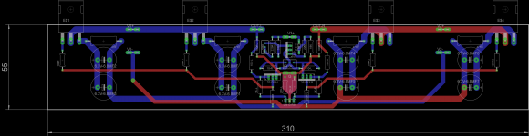
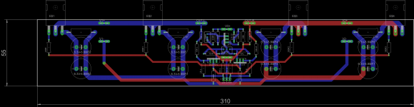
Looks like this will do the job very nicely but two things need attention:
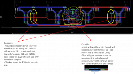
The 100r virtual grd resistors need more space - they are large 3-5 watt parts and so may be useful to make space for a parallel set. We an use that later for tweaking too if we want but at the min need more space for a bigger part. The common point for these two 100r needs to be separate from the other earth connections - carries quite a bit of juice etc - you know the drill.
The input diff pair if you can line em up btb or same alignment would be bonus so we can tie em together to min drift. Not a big issue at all and it complicates layout a heckuva lot so I m not losing sleep over this.
Looks like this will do the job very nicely but two things need attention:
The 100r virtual grd resistors need more space - they are large 3-5 watt parts and so may be useful to make space for a parallel set. We an use that later for tweaking too if we want but at the min need more space for a bigger part. The common point for these two 100r needs to be separate from the other earth connections - carries quite a bit of juice etc - you know the drill.
The input diff pair if you can line em up btb or same alignment would be bonus so we can tie em together to min drift. Not a big issue at all and it complicates layout a heckuva lot so I m not losing sleep over this.
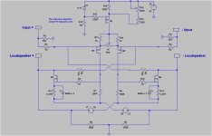
If you replace the diff pair CCS with a resistor, the common mode voltage of the drain resistors will swing with signal.
The cascode FETs are there for good reasons, as the drain voltage sees the complete output swing, and more.
Patrick
Patrick thanks - I will try removing the CCS at some point later just to see if things break. I suspect there should not be too many problems since the common mode voltages will get nailed by the differential nature of the outputs.
Anyway no harm playing with this 😀 so lets see.
I will report later what I find either way once I get round to it. It will be nice to understand the merits/otherwise of deleting yet another part.
On cascoding - points noted but not sure how much of a practical improvement we will see, given the already good linearity of the basic setup. Gilding the lilly maybe but certainly worth a go if we're going down the road of adding parts - hopefully for another amp down the road.
Thanks again for the inputs. Cheers, Kasey
Last edited:
schematic
gremlins crept in - I noticed an error in the schematic in post 28 http://www.diyaudio.com/forums/pass...regation-pass-inspired-ideas.html#post3589261
while debugging the pcb layout with buzz.
Pls see update drawn below - this will be cleaned up and more details added later after PCB tests.
gremlins crept in - I noticed an error in the schematic in post 28 http://www.diyaudio.com/forums/pass...regation-pass-inspired-ideas.html#post3589261
while debugging the pcb layout with buzz.
Pls see update drawn below - this will be cleaned up and more details added later after PCB tests.
Attachments
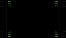
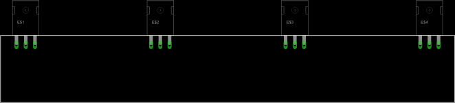
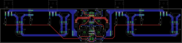
Another try. I can move the neg rail mounts to middle of lower large bus if you like it better. I can add the ground pin back in for the input, but Rane suggest attaching directly to case. Its up to you.
http://www.rane.com/note110.html
http://www.rane.com/note110.html
Attachments
Last edited:
Looks a beaut.
Psu connector layout is better your way than mine.
Ground pin and earth connections let me get back to you.
Psu connector layout is better your way than mine.
Ground pin and earth connections let me get back to you.
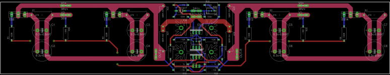
That's the bizness Buzz- Looks great !
Ill build up a set with these and see where we end up.
Doesn't look to me like many people build circlotrons - I'll try and find out why (and document it here) so folks can decide whether there's any attraction here (or not)
Meantime the transformer is here😉
Big heavy beaut - 8 x 18V 4A plus two low power 20v 0.1a rails for the ccs.
I plan to set it up so we can do two modes:
i) high current mode for ger and esl/ribbon guys so 24V 8a rails
ii) normal mode for 4 ohm and up speaks so that will get 48V rails.
Lets see if it blows up or not 😉
Attachments
Very nice I can't wait to see the results.
In my current combination I use about a 1:250 step-up ratio and 20Vpeak signals is more than enough and is about max the panel can handle.
Typically 5-10v Peak is more than ample for normal listening with my system.
10V peak signals get me about +99db!!!
Sorry for repeating my self! He,he,he 🙂
Thank You, For including this in your testing!!!!
jer 🙂
:Ger sure - I think the low voltage hi current version should do the trick - fingers crossed and lets see. So far I have not tried dual outputs so its still an unproven idea. Looks like it is worth a good go I reckon. Just for my info - whats the impedance of your setup at about 100Hz or so - there's usually not much below musical content below that anyway i think ?
Buzz - bit rich of me to ask given that you did so much work on the PCBs - how long do you think the shop will take to do a small run of the boards ? Soldering iron is getting antsy... 😀
Buzz - bit rich of me to ask given that you did so much work on the PCBs - how long do you think the shop will take to do a small run of the boards ? Soldering iron is getting antsy... 😀
Money makes things faster, of course. Ill send what I have so far and other options I have found.
Kasey197,100hz is quite low at about .75 ohms or so for those using two of the Anteks.
Typically ESL's (at least mine) are crossed over in the 300Hz to 600Hz range or higher.
Actually about 1100Hz for my desktop version.
So for two cores this is above about 1 to 2 ohms until about 10Khz to 20Khz.
For most of the DIYer's here refer to these impedance charts for an unloaded transformer to give you an idea only divide the impedance by 2 because it is only for one core,
http://www.diyaudio.com/forums/planars-exotics/161485-step-up-transformer-design-6.html#post3404300
Between those frequency ranges it is safe for nearly any amplifier except for the fact that it is very reactive and stability may be an issue for some.
My Cheapy Awia 80watt amp doesn't have any issues within this range it is just on the extreme ends of the scale is where it starts to struggle as crossover distortion is very pronoun due to the high current demand and becomes unstable as the protection circuits shut it down.
I have all of this documented in another thread.
At the lower frequency's the low impedance is caused from the transformer itself due to the low inductance of the primary winding.
At this point the ESL has little to no effect on the impedance because it is very high impedance at low frequency's, Therefore all of the power in this range is wasted as heat in the core.
The lowest one can go with an average power toroidal transformer is about 330Hz with a 40Vrms (60vpeak) input signal, below this frequency the core starts to saturate and it is like presenting a short to the amplifier and the current draw goes through the roof.
The relationship between frequency and voltage level is linear.
For instance if one wanted to go as low as 165Hz for a crossover point then the most voltage you can apply to the primary winding would be no more then 20Vrms, and, so on.
This equates to the 6V at 60hz that it is designed for as well for a 240v/6v type transformer.
As tested they generally have a little wider range of tolerance than what theory predicts.
As in my example in the previous post if I wanted to use a 1:128 step-up ratio then I would need double the voltage swing to 20Vpeak (or 40Vpeak for the maximum) to reach my goal.
However, This lower ratio does raise the impedance to a nicer range but the amplifier must swing twice the voltage.
Only in rare cases (depending on ones setup) does the impedance get below 1 ohm and would only be for the intermittent peaks in the 10Khz to 20Khz range.
I have more issues at the lowest frequency's than I do at the higher ones.
It took me a long time to grasp what is going on, But it really is quite simple now that I understand it.
I have been contemplating a massively paralleled chipamp design but I would rather use a Class A type output stage.
From what I understand they work very well for such a difficult load.
Besides the concept of it being Class A appeals to me very much as well.
A high current Aleph X is one that I had in mind, But your configuration cuts the number of output devices in half and gets the job done with a much lower THD.
I have just the transformer for such a setup that came out of a PDP 11/70 mainframe computer and it has 6 (I think, maybe 8) separate 20v-30v CT windings on it at about 1600va or so.
I have been testing these FETS from TI,
http://www.ti.com/lit/ds/slps362a/slps362a.pdf
It worked very nicely to drag down my 15V supply to about 12V maintaining about 15 amps as the only load on it with no resistor in series and just the FET alone across the supply.
I took only about 2.5V of gate voltage to do so as well.
I tried it on a 32V supply and it worked nicely until I slipped with the gate voltage control and maxed it out and shorted it.
My meter showed an excess of 20amps (maximum for my meter)when it went bad as it was a linear test and not a pulsed test.
Now I only have 2 out of 3 but I will get some more and continue testing them.
They are very nice for only $.71per 1000.
$2.71 at Digikey.
The CSD18532KCS's have a little higher rating as well as 190 amps and 216 watts but they have nearly double the gate capacitance.
This shouldn't much of a problem since only .7v p-p signal on the gate is all that is required to make them swing 15 amps or so.
I will also look into what ST has to offer as well.
jer 🙂
Last edited:
Ger, thanks for the patient and detailed explanation - I think I get it.
As for the fets - those are nice ideas (not sure about the To-220 fet though) and the reality is that there are literally thousands that you can try since we do not need complementaries.
The amp has a very basic topology so the specific fet type you choose will be heard and measured quite readily.
It does work though with almost anything of the correct polarity and wattage 🙂
Whether folks feel that this.. err... "transparency" (to put a positive spin on it) is desirable is a matter of perspective though. One of hallmarks of good design I was thought at E&E school yonks ago was to immunise the design to device selection.
This neutralisation though takes even more parts and more complexity and therefore I guess I'd fail that test.
I went through about a dozen front end parts and another 10 parts for the input LTP - takes time but is easy to try if youre inclined. For outright messing with fet ops though i think the F6 is the best platform there is because there are no driver stage Gm vs Id Vs output Vth interactions to have to deal with.
If not, you can just use what I did for a start and go from there 🙂
Will post results for some of the more interesting ones later incl. our favourite workhorse, the IRF240. cheers,
Last edited:
- Status
- Not open for further replies.
- Home
- Amplifiers
- Pass Labs
- The Valorous Amp - A modest aggregation of pass inspired ideas