I am going on vacation and can give it a shot. Let me know if you have any specific request layout wise.
buzz thanks that would be fab! No real asks re layout other than hopefully making it single layer and maybe an option for another set of outputs in parallel. I'm hoping to get the op up from 60W to 100W/8R.
Whatever you can come up with we can tweak later pretty easily i'm sure.
PS> Only if you have time after family affairs during the much deserved vacation!
Whatever you can come up with we can tweak later pretty easily i'm sure.
PS> Only if you have time after family affairs during the much deserved vacation!
No problem. Just sitting around in mountains in 75F weather😀. Will not promise anything great, but as you say, it can be tweaked.
guys i was pointed to this thread that has a lot of very interesting discussion abt this type of amp:
http://www.diyaudio.com/forums/pass-labs/78734-new-tron.html
Like the flu - circs seem to pop up every so often 🙂
http://www.diyaudio.com/forums/pass-labs/78734-new-tron.html
Like the flu - circs seem to pop up every so often 🙂
This is a very interesting thread as I have been wanting to explore this topology many times.
I have designed something very similar in Circuit maker only it didn't use the circlotron type of output configuration.
It was more of a standard Class B push pull configuration feeding a center taped winding.
Like this,
http://www.diyaudio.com/forums/pass-labs/78734-new-tron.html#post905780
Only I had no idea this existed in these threads until now.
I will try to find my original design if I can as it is on another hard drive somewhere.
I did my version in 2010.
But, For us ESL people we need something that will handle impedance's down to 1 to 2 ohm range or so, What are your views on this?
The THD figures are very impressive for sure, But what happens to them is the impedance gets lower?
I will read this thread in much more detail so that i fully understand it, as I just had these couple of questions.
Thanks!
jer 🙂
Last edited:
@Kasey
Look at post #7 Went over in that thread without even an acknowledgement. Very interesting idea, IMO.
Look at post #7
Went over in that thread without even an acknowledgement. Very interesting idea, IMO.....But, For us ESL people we need something that will handle impedance's down to 1 to 2 ohm range or so, What are your views on this?
The THD figures are very impressive for sure, But what happens to them is the impedance gets lower?
I will read this thread in much more detail so that i fully understand it, as I just had these couple of questions.
Thanks!
jer 🙂
Hi Jer,
I think the loading due to the low impedance is certainly one issue but the more pernicious problem is that the ESL load looks capacitive to the amp. Many (not all not all!) ab amps don't seem to like this very much. I think it tends to screw around with their carefully compensated FB loops by introducing unwanted poles. VI limiters effects are also at play here according to this: Heavy Load: How Loudspeakers Torture Amplifiers | Stereophile.com (shows quite vividly how demanding ESLs can be.)
This amp will certainly have higher distortion figures at lower loads (almost all amps do) so maybe you want to parallel some output mosfets if that turns out to be a problem.
Otherwise I think this one will enjoy itself quite nicely with an ESL - for one thing its stableinto heavily capacitive loads. Well at least the prototype is 😀
Note that the square wave was made into a 3uF load paralleled with an 8R resistor. At 20khz - that cap itself has an impedance of less than 3 ohms....
Last edited:
@Kasey
Look at post #7
zm predates all 😀

thd+n into 2R
As requested here it is into a 2R load.
The lab PSU's are limited to ~3A each rail so measurements at higher W are probably wonky.
At lower powers looks about what I'd expect.
Will have to wait till final build for a better read on this. But yeah it works fine into low-r loads.
As requested here it is into a 2R load.
The lab PSU's are limited to ~3A each rail so measurements at higher W are probably wonky.
At lower powers looks about what I'd expect.
Will have to wait till final build for a better read on this. But yeah it works fine into low-r loads.
Attachments
Cool....Thank you, For looking at this for me!!
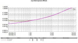
Here is a typical impedance plot of just one transformer (Antex1206) that we have been using.
This plot is of just one transformer so the impedance's will actually be half of those shown in the graph for two of them because the primary's are in parallel.
http://www.diyaudio.com/forums/planars-exotics/161485-step-up-transformer-design-6.html#post3404300
So, On the low frequency side (the left side of the peak) the reactance is inductive and the capacitive load of the panel has little effect, But this would be about 1 ohm at 300hz and 2 ohms at about 600hz (550hz on the graph).
The plot shown is for an unloaded transformer.
The impedance on the right side of the peak now starts to become a capacitance reactive load as the frequency is raised.
On a fully load transformer this impedance can dip into and below 1 ohm at 20Khz determined by how big the panels are and how much capacitance they have plus the step-up ratio of the transformer.
In my current system using similar transformers (actually better curves that are higher even at 1:256 step up ratio), my panels are only about 50pf max and have little effect on the loading and the impedance is almost purely caused by the transformers themselves.
It takes no more than about 5v peak to make a good easy listening comfortable sound with my little 10" X 3" panels with 1:256 step-up ratio.
I have measured about +99db with 10v peak signals, and, a pretty loud +105db at 20v peak with test tones at 1 meter.
Using my my cheapy class AB amp 10Vpeak is about the limit it can do.
Above this it starts to struggle and its protection circuits cause it to shut down.
At this point Crossover Distortion is very evident and gets worse as more current is demanded from it.
At 20v peak levels (and RMS) and above it will even bring my Crown DC300a to its knees due to the low impedance, This causes the amp to get very hot.
At those levels it is uncomfortably loud even with just music and approaches the voltage limits of the stator coating limits.
I use about 7Kv of bias on those little panels.
A larger panel system will have similar performance only at a lower voltages and step up ratios applied to the stators due to the increased surface area but the load will be as I described earlier due to two cores being used.
This is a typical load for an ESL system just to give you an idea.
Highly reactive low ohm loads but only at each of the extreme Hi/Lo ends of the frequency scale.
A properly designed transformer would only have low impedance's at the highest frequency's but this is not the case for us DIYer's.
As long as the amp is stable for these intermittent intervals of low impedance's is all that matters.
Although operation at the lowest frequency's are more constant due to the content of music material.
It looks like a very viable and suitable simple design that shows great potential of performance, especially for lower normal listening levels with ESL's.
The THD figures are Great!!!!
I tried to find the circuit I was working on in my archives but it is not on my current drives, so I will have to hookup and search some of my other ones to find it.
Thank you for your time!!!
jer 🙂
Last edited:
Good grief - these curves seem designed to kill
Amplifiers that is
Maybe like praying mantis
One must lose its head
Amplifiers that is
Maybe like praying mantis
One must lose its head
On a more serious note - think you'd be safer seeing off this sort of load with 2 outputs not one. Min. Or maybe a F4 style follower if that suits.
Edit: will try dual outputs and let you know e results once the single ops amp is completely baked.
Edit: will try dual outputs and let you know e results once the single ops amp is completely baked.
Last edited:
Oh Yes, Definitely more than one set of outputs for sure!!!
I was considering an F4 but I do want to stay away from designs that use obsolete and hard to find components.
Typically input JFET's.
jer🙂
I was considering an F4 but I do want to stay away from designs that use obsolete and hard to find components.
Typically input JFET's.
jer🙂
Last edited:
I think the loading due to the low impedance is certainly one issue but the more pernicious problem is that the ESL load looks capacitive to the amp. Many (not all not all!) ab amps don't seem to like this very much. I think it tends to screw around with their carefully compensated FB loops by introducing unwanted poles. VI limiters effects are also at play here according to this: Heavy Load: How Loudspeakers Torture Amplifiers | Stereophile.com (shows quite vividly how demanding ESLs can be.)....
Thanks for the link, very instructive. Where do I go to join SCAMP—the Society for Cruelty to Amplifiers ???
Perhaps you might be interested in this from 2006 :
http://www.diyaudio.com/forums/pass-labs/78734-new-tron-2.html#post925332
You can of course use 2SJ103 (still very easy to get) for the diff pair current source.
And if you insist, use a P-MOS for the diff pair, such as 2SJ148, or ZVP3310, or similar.
Or 2SJ313 if you want to use tO220.
Patrick
http://www.diyaudio.com/forums/pass-labs/78734-new-tron-2.html#post925332
You can of course use 2SJ103 (still very easy to get) for the diff pair current source.
And if you insist, use a P-MOS for the diff pair, such as 2SJ148, or ZVP3310, or similar.
Or 2SJ313 if you want to use tO220.
Patrick
Ooooo very sexy Patrick!
Some quick questions if you don't mind
- if we restrict ourselves to balanced inputs ONLY, we can ditch the ccs altogether right ? I think that it should be ok and sims agree ? What do you/anyone else reckon ?
- in your cct, if we use p-mos for the LTP, can we ditch q2/q3 as we no longer have the voltage restrictions of the j109 to deal with ? Of course then we will miss out on the svelte touch of these lovely jfets agreed.
Thanks!
If you replace the diff pair CCS with a resistor, the common mode voltage of the drain resistors will swing with signal.
The cascode FETs are there for good reasons, as the drain voltage sees the complete output swing, and more.
Patrick
The cascode FETs are there for good reasons, as the drain voltage sees the complete output swing, and more.
Patrick
- Status
- Not open for further replies.
- Home
- Amplifiers
- Pass Labs
- The Valorous Amp - A modest aggregation of pass inspired ideas