Ok, I just realised you left the center tap of the transformer unconnected.
However, according to the schematic in the magazine article posted earlier, the centre tap should be connected to GND. Without this GND reference, the floating PSU potential will just follow the audio AC signal applied to the power tubes. There will be essentially no audio signal across the speaker.
Good surprise 😀 : the power output that I have on a 16R load reaches 12.5W RMS... And it even works loudly when connected on a speaker with music (small JVC SP-MX30BK bookshelf test speaker) 😱 😉

A+!
Sure. I just don't understand how this can be if the power supply is floating relative to the speaker GND. Are you SURE you didn't connect the PSU as shown in the magazine article?
Sure. I just don't understand how this can be if the power supply is floating relative to the speaker GND. Are you SURE you didn't connect the PSU as shown in the magazine article?
Sure @mbrennwa : I connected my PSU according to the schematic below - add in your mind the non-traced 12K/7W in // with upper and lower filter capacitor :

Moreover, I saw that you developped an audio analyser (MATAA) : is this software able to measure and analyse distortion ? If yes, that would be interesting to me...
A+!
Last edited:
Well, I will say that I don't see how your PSU/GND scheme can work and leave it there.
Yes, MATAA can do all sorts of distortion analysis. What do you have in mind?
Yes, MATAA can do all sorts of distortion analysis. What do you have in mind?
Last edited:
The Toobz & Caps form a bridge, unhooked from gnd. Probably gets a bit weird when NFB is hooked up tho from the point where the Toobz connect to the speaker.!!🙂
Seems like the reference iz floating. Maybe not.
Seems like the reference iz floating.
Maybe not.Well, I will say that I don't see how your PSU/GND scheme can work and leave it there.
Yes, MATAA can do all sorts of distortion analysis. What do you have in mind?
Thanks @mbrennwa, 🙂
I sent a PM to you and contacted you also via your website.
My idea is to drive the (real) amp (or a stage of the amp) with a reference signal generated by the computer and analyse it via the computer to qualify the harmonics order, THD, IMD, Phase, bandwith... That's what could do SpectraLAB via my DIY interface box :
A+!
The Toobz & Caps form a bridge, unhooked from gnd. Probably gets a bit weird when NFB is hooked up tho from the point where the Toobz connect to the speaker.!!🙂
Seems like the reference iz floating.
That's it. 🙂
A+!
My idea is to drive the (real) amp (or a stage of the amp) with a reference signal generated by the computer and analyse it via the computer to...
Sure. Just take a look at the manual to see if MATAA is right for you.
OK - I have measured all the DCV and Sig.V TRMS on my prototype before modding.
Idle current is still 300mA, @10WRMS output = 438mA
Now I will experiment @Ketje's suggestions to see if I have better results.
Wait and See... 😉
A+!
Idle current is still 300mA, @10WRMS output = 438mA
Now I will experiment @Ketje's suggestions to see if I have better results.
Wait and See... 😉
A+!
@Ketje suggestions test : RESULTS
1 - searching the adequate preamp stage Rk and Rp (12AX7 // sections) :

The images below shows it all (please zoom 😀) :

A comparison side-to-side original circuit vs. modded 1K5 220K circuit :

Verdict : the best result is offered with Rk=1K5 and Rp=220K, and not 2K2 or 2K7. The linearity is slightly improved (not easy to see) versus the original circuit, and moreover the input headroom is increased by the higher Rk value. No signal change (in or out) occurs.
2 - Moving the -H bias pot return from GND to SPKR output line, decoupling the pot with a 100µF capacitor :

Verdict : this moving nulls a permanent 100mVDC offset at the speaker output (at idle or full power, 16R load), but the capacitor is unnecessary, since it has no noticeable effect. The signal remains the same at the input and output, even with 10Hz square wave signal, where the decoupling cap may have had an influence.
Thanks again @Ketje for your suggestions. 😉
Tomorrow I'll wire all this properly, update my schematic and measure all DC and ACV... 😎
Wait and See ! 🙂
A+!
1 - searching the adequate preamp stage Rk and Rp (12AX7 // sections) :
The images below shows it all (please zoom 😀) :
A comparison side-to-side original circuit vs. modded 1K5 220K circuit :
Verdict : the best result is offered with Rk=1K5 and Rp=220K, and not 2K2 or 2K7. The linearity is slightly improved (not easy to see) versus the original circuit, and moreover the input headroom is increased by the higher Rk value. No signal change (in or out) occurs.
2 - Moving the -H bias pot return from GND to SPKR output line, decoupling the pot with a 100µF capacitor :
Verdict : this moving nulls a permanent 100mVDC offset at the speaker output (at idle or full power, 16R load), but the capacitor is unnecessary, since it has no noticeable effect. The signal remains the same at the input and output, even with 10Hz square wave signal, where the decoupling cap may have had an influence.
Thanks again @Ketje for your suggestions. 😉
Tomorrow I'll wire all this properly, update my schematic and measure all DC and ACV... 😎
Wait and See ! 🙂
A+!
Last edited:
I think it is the infuence of changing Rk on the current in the ECC82 (caused by the DC-coupling) that makes the difference.With 2k7 the ECC82 is somewhat over 6mA and with 1k5 only 4,5mA.To balance that current the bias resistor has to be adapted.Verdict : the best result is offered with Rk=1K5 and Rp=220K, and not 2K2 or 2K7. The linearity is slightly improved (not easy to see) versus the original circuit, and moreover the input headroom is increased by the higher Rk value. No signal change (in or out) occurs.
The problem with DC coupling, everything changes everything.
Yes, makes only very little change.The ΔVout being much smaller then Δ-Vg.It's more cosmetic.2 - Moving the -H bias pot return from GND to SPKR output line, decoupling the pot with a 100µF capacitor :
Verdict : this moving nulls a permanent 100mVDC offset at the speaker output (at idle or full power, 16R load), but the capacitor is unnecessary, since it has no noticeable effect. The signal remains the same at the input and output, even with 10Hz square wave signal, where the decoupling cap may have had an influence.
Mona
Oscillgrams and measurement on the new version :


I thought I would find a slightly higher bias at the 12AX7 // : it only raised from 0.643V (560R 100K) to 0.874V (1K5 220K). All other things being equal, it improved the linearity, so that's fine.
A friend of mine (the Guy who built the cathode bias OTL I pictured some posts before) is now working on a bootstrap preamp for this circuit.
Wait and See ! 😉
A+!
Oh, I forgot to make a bandwith measurement... Let's go :
I set up the same conditions as with the pre-mods circuit, where I recorded and checked a 1Hz - 250KHz @-3dB, output ref. 10.00V 16R 1KHz sinus.
Surprise : the bandwith collapsed to 1Hz - 75KHz... 😕 This is also confirmed by the square waves that are neatly more integrated now.
I'll recheck my measurement again, then go back to the original circuit and I'll probably discover the source of that bandwith drop !
Wait and See ! 😉
A+!
That's to be expected with the anode resistor from 100k to 220k, but not that much.Oh, I forgot to make a bandwith measurement... Let's go :
I set up the same conditions as with the pre-mods circuit, where I recorded and checked a 1Hz - 250KHz @-3dB, output ref. 10.00V 16R 1KHz sinus.
Surprise : the bandwith collapsed to 1Hz - 75KHz... 😕 This is also confirmed by the square waves that are neatly more integrated now.
I'll recheck my measurement again, then go back to the original circuit and I'll probably discover the source of that bandwith drop !
Wait and See ! 😉
A+!
Another thing, as I said before, your 12AX7 seems to be rather week.
Look what you shoud get, only 85V on the anode.
Mona
Attachments
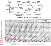
I checked a plate current on each triode a 1.1mA for a datasheet spec at 1.2mA @-2V : IMHO, such a tube can't be qualified as weak... Right ?
But OK : I will test with another ECC83 at exactly 1.2mA or more, who knows ? I'm not sure that it would give a great improvement, though...
Let's see all this tomorrow ! 😀😉
A+!
But OK : I will test with another ECC83 at exactly 1.2mA or more, who knows ? I'm not sure that it would give a great improvement, though...
Let's see all this tomorrow ! 😀😉
A+!
The model agrees with your measurement with some small variation.
@Brice : That's interesting. 🙂
Can you draw the frequency response of the circuit on 16R load ?
I measure 1Hz - 75KHz @-3dB with my scope.
How much do you find by simulation ?
Thanks ! 🙂
A+!
The model shows more: 1Hz to 250KHz at -3db.
Here is a Fourrier analysis at 1K @ 0.1V input.
Direct Newton iteration for .op point succeeded.
N-Period=10
Fourier components of V(spkr)
DC component:0.000436605
Harmonic Frequency Fourier Normalized Phase Normalized
Number [Hz] Component Component [degree] Phase [deg]
1 1.000e+3 1.861e+0 1.000e+0 -179.77° 0.00°
2 2.000e+3 4.851e-3 2.607e-3 91.96° 271.73°
3 3.000e+3 2.447e-4 1.315e-4 172.82° 352.59°
4 4.000e+3 4.595e-6 2.470e-6 -4.39° 175.38°
5 5.000e+3 2.981e-4 1.602e-4 38.91° 218.69°
6 6.000e+3 1.144e-4 6.147e-5 26.68° 206.45°
7 7.000e+3 4.873e-4 2.619e-4 -115.15° 64.62°
8 8.000e+3 1.160e-4 6.234e-5 -48.25° 131.52°
9 9.000e+3 1.439e-4 7.734e-5 54.11° 233.88°
10 1.000e+4 1.221e-4 6.562e-5 -151.11° 28.67°
Total Harmonic Distortion: 0.263158%(0.284465%)
I attached the LTSpice simulation.
Attachments
The model shows more: 1Hz to 250KHz at -3db.
Total Harmonic Distortion: 0.263158%(0.284465%)
Amazing, @Brice ! The 1hz-250KHz is the bandwith that I had checked with my non-modded prototype... 😱
Sure, @Ketje is right : a RL shift from 100K to 220K inevitably alters the bandwith, but such a 250KHz to 75KHz drop is suspect... I'll have to retest all the stuff, in order to know if it's me 😡 or the circuit 😕😱 !
The THD you mention is for a low watt output : can you simulate for a 0.727VRMS input @1KHz ? You should find circa 10.00V output on 16R.
Thanks ! 😉
A+!
Last edited:
Models of toobz in Spice are far from perfect & at times don't accurately predict distortion in the finished cct. Results should be taken as a guide, not the final result.🙂
- Home
- Amplifiers
- Tubes / Valves
- The ultimate OTL6080