On tube amps, here is what I do.
HF stability tests are performed using a 1 watt 10 kHz square wave (as measured when normally loaded) with scope hung on the output, and then the output shorted, opened, or operated in a capacitance only load ranging from .005uF to 1.0uF.
At some value, the cap only load will certainly produce a maximized ring on the tops and bottoms of the square waveform, but should never cause it to break into full blown oscillation.
Ah, OK @Brice, I see : thanks ! 😎
I will perform exactly the same test as yours, if I understand the protocol well :
step 1 - 1W@10KHz/16R = reference calibration (for my amp).
step 2 - output shorted test
step 3 - output open test
step 4 - output loaded with a cap only test, ranging from 5nF to 1µF.
Checking for overshoot and oscillations on tops and bottoms of the square wave in step 2, 3 and 4.
Let's go...
I'll post the matching oscillograms for comparison. 😉
A+!
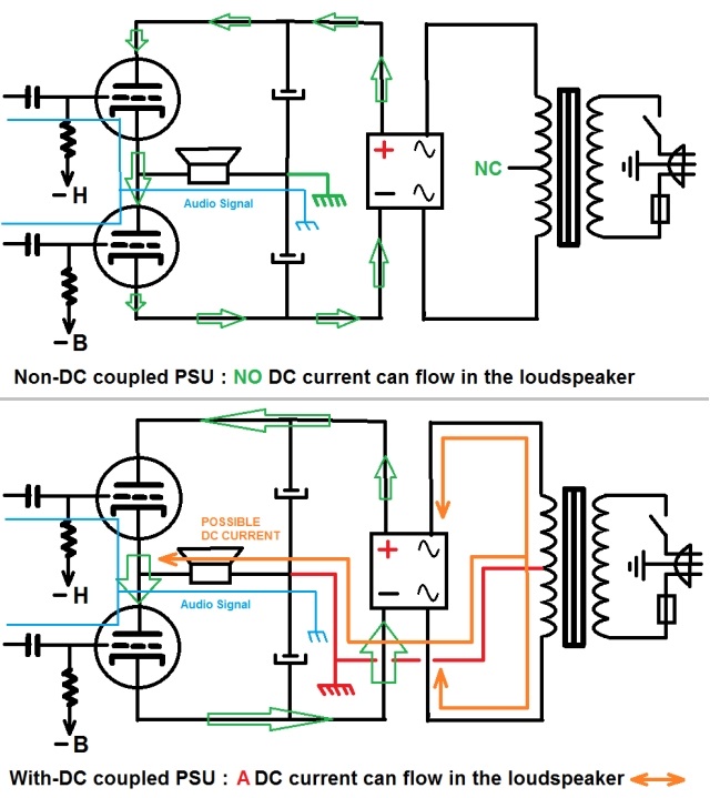
Yes, it's the common belief about OTL amps to be suspicious about the DC offset risk in the speaker output inducing damage.
In fact, it mainly depend on the output stage and PSU configurations : some maybe dangerous - requiring a safety circuit - others not...
I'll post a schematic about that soon. 😉
A+!
I am extremely interested in your project. Please keep us updated.
I personally skip the short test. Even at 1W I do not like to do this.
For an amp with an output impedance this high, like most OTLs, is it not enough to load it with 1ohm or so? Relative to the output Z that must surely be close enough to a short. Then again I do not see any reason to test an amp into a shott. A few uF of capacitance must surely be as tough a test that is ever needed.
Tubeelectron, I like your website. Are those guitaramps and effects your builds? Amazing stuff very well done.
I also like this OTL project and am looking forward to more of your experiments. I have a few nonstandard OTL designs and even made some for guitar.
I also like this OTL project and am looking forward to more of your experiments. I have a few nonstandard OTL designs and even made some for guitar.
@Brice :
Here are the results of the square wave stability test according to your procedure suggestion :

The circuit apparently show no trace of instability here... 😎
A+!
Here are the results of the square wave stability test according to your procedure suggestion :
The circuit apparently show no trace of instability here... 😎
A+!
I am extremely interested in your project. Please keep us updated.
Yes. Sorry to be late, I had to draw it : here is the difference between a "good" OTL supply and a "bad" one in terms of possible DC current flowing in the speaker in case of damage in the tubes :
Well, I really thought that apart for @Brice and me, that OTL subject was of no interest...
A+!
For an amp with an output impedance this high, like most OTLs, is it not enough to load it with 1ohm or so? Relative to the output Z that must surely be close enough to a short. Then again I do not see any reason to test an amp into a shott. A few uF of capacitance must surely be as tough a test that is ever needed.
Well, since I had really no experience in stability testing, I started first with 27µF // 16R (16R being the nominal load that I admitted for my prototype). I think that probably this test - done at max output power - was finally much more severe than the @Brice's procedure... 😕
The protocol described by @Brice seems to be the testing norm about square wave stability, that's why I tested it also, for comparison.
If the amplifier below is reputedly offering a satisfactory capacitive load stability (as mentioned in the French text, sorry) :

I think that my OTL circuit is then rather "rock stable" ! 😀
A+!
Tubeelectron, I like your website. Are those guitaramps and effects your builds? Amazing stuff very well done.
I also like this OTL project and am looking forward to more of your experiments. I have a few nonstandard OTL designs and even made some for guitar.
Thanks @SemperFi ! 😉
Yes, these are my builds. but please note that it is a non-commercial website, but an amateur one. 🙂
Sure ! There is not only one way to build an OTL amplifier - notably depending on the power your expect from your amp.
The only two variants I tested are the SEPP type and some CircloTron types too - that is to say somewhat standard designs - at least in the general principle.
It seems to me that the CircloTron circuit is well regarded these times, more than the SEPP type...
But it's me, OK ? 😀
A+!
Where is the schematics of this Amp?
Here are the basics :
https://patentimages.storage.googleapis.com/27/ae/da/f8849d71d627f2/US2773136.pdf
This is the original Julius Futterman circuit, patented in Dec. 1956. That's exactly the base that I started from to design my prototype here.
This is a very simple and efficient design... Thank your Mr Futterman !

A+!
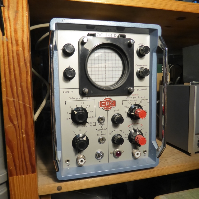
I also redone today a square wave test at full power using more "modern" equipment than my venerable "Constructions Radioélectroniques du Centre" (aka CRC, now Thalès) oscilloscope, a NOS French Navy model (in which I trust blindly... 🙄) :
Here's the gear now : 2x60MHz scope and function generator...
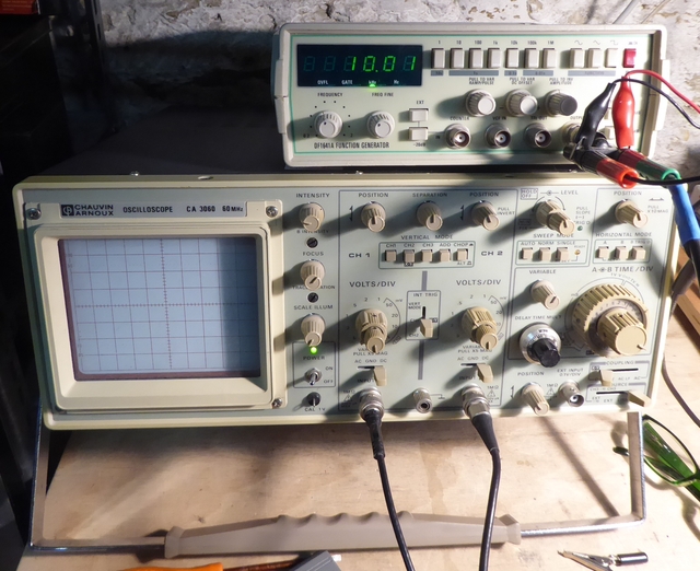
And the matching waveforms (reference = 10.00V True RMS 1KHz 16R) :

Not so very far from my vintage CRC scope and Leader Wien bridge, finally... 😉
A+!
Here's the gear now : 2x60MHz scope and function generator...
And the matching waveforms (reference = 10.00V True RMS 1KHz 16R) :
Not so very far from my vintage CRC scope and Leader Wien bridge, finally... 😉
A+!
Some refinements made today... 😉
After several tests, I changed the preamp Rk from 750R to 560R and removed the 220µF decoupling capacitor, introducing a local intensity NFB.
No improvement found in modifying the Cathodyne phase splitter loads value : distortion increase (lower values) or less drive (higher values), so 18K appears to be the best.
Finally, the linearity, the distortion and the clean headroom before clipping are noticeably improved, as it can be seen on the oscillograms below... 😎
Too bad : I have no mean to measure and qualify the distortion for the moment 🙁, but I don't think that I have more than a few percents at maximum power...
Triangle wave :

Sine wave :

Square wave :

Here's the matching schematic of the circuit as tested today (sorry, it took me some time to redraw it), derived from Julius Futterman 1956 patent :

As you can see, it's very simple - just like Mr Futterman's original design... 😉
A+!
After several tests, I changed the preamp Rk from 750R to 560R and removed the 220µF decoupling capacitor, introducing a local intensity NFB.
No improvement found in modifying the Cathodyne phase splitter loads value : distortion increase (lower values) or less drive (higher values), so 18K appears to be the best.
Finally, the linearity, the distortion and the clean headroom before clipping are noticeably improved, as it can be seen on the oscillograms below... 😎
Too bad : I have no mean to measure and qualify the distortion for the moment 🙁, but I don't think that I have more than a few percents at maximum power...
Triangle wave :
Sine wave :
Square wave :
Here's the matching schematic of the circuit as tested today (sorry, it took me some time to redraw it), derived from Julius Futterman 1956 patent :
As you can see, it's very simple - just like Mr Futterman's original design... 😉
A+!
Uber super.
Thanks, @Brice !
Well, this is a too simple circuit
 , not enough Audiophile to be interesting 😱... Too bad, Mr Futterman 🙁... 😀😀😀
I started the BOM, and I'll do some more serious comparative listening tests soon, hoping that I won't have bad surprises ! 😕
Wait and See... 😉
A+!
Ha ha.
Just a question: why are the coupling caps so big?
I got the RC period but why only 56K on the bias network?
(I know, it's my DC coupled head talking 😉 )
Thank you.
Just a question: why are the coupling caps so big?
I got the RC period but why only 56K on the bias network?
(I know, it's my DC coupled head talking 😉 )
Thank you.
Ha ha.
Just a question: why are the coupling caps so big?
I got the RC period but why only 56K on the bias network?
(I know, it's my DC coupled head talking 😉 )
Thank you.
Yes @Brice - easy :
1 - Even if the two oscillograms below are not taken with identical setup adjustment, the difference in slope is visible : at left 1µF, at right 10µF.

For a reasonable low end square wave transmission, I noticed that at least a 10x lower RC constant (or frequency) was needed at the coupling. Hence the big 10µF... That will take an important room in my small chassis format !
2 - The 6080, along with 6C33C, 6336, etc... Are high perveance tubes and tend to give some grid currents (typically 1-4µA for a 6080) that increase when driven in class AB and even more in class B.
So you need to let this current flow through a quite low Rg, otherwise the following tube bias will be affected under modulation peaks and the driver can clip earlier due to adverse voltage and current at the 6080 grids, increasing distortion and lowering the clipping threshold.
That's why I use low common grid resistor for the 3x 6080 here, along with // ECC82 to lower impedance driver (Futrterman used a 6C4A tube here).
A+!
Got it. Makes total sense.
Thank you.
Brice.
Well, if you have an idea to avoid those 10µF by a direct coupling to the 6080 with a simple solution, I'm interested, of course... 😎
But I'm afraid that this conversion to DC coupling would be difficult to achieve without turning the circuit into an usine à gaz... 😕
A+!
- Home
- Amplifiers
- Tubes / Valves
- The ultimate OTL6080