@Ketje - thanks !
Yes, returning the lower bias to the phase splitter instead of GND was a test that I should do also. Futterman did not do that, but some japanese schems do that.
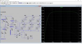
For the moment, I am working on ripple tests on the +115/-115.
Some questions :
1 - For determining the new values that you suggest, did you take in count that the 12AX7 and 12AU7 have their two triode sections paralleled ?
2 - Also, what is the purpose of the 10µF 63V across the A10K pot ?
Sorry, @Brice : I'll look at your simulations in the late evening : the web lags too much now... It's a chance that I could open @Ketje schem !
I return to my bench...
A+!
Yes, returning the lower bias to the phase splitter instead of GND was a test that I should do also. Futterman did not do that, but some japanese schems do that.
For the moment, I am working on ripple tests on the +115/-115.
Some questions :
1 - For determining the new values that you suggest, did you take in count that the 12AX7 and 12AU7 have their two triode sections paralleled ?
2 - Also, what is the purpose of the 10µF 63V across the A10K pot ?
Sorry, @Brice : I'll look at your simulations in the late evening : the web lags too much now... It's a chance that I could open @Ketje schem !
I return to my bench...
A+!
Oh, the AX and AU have their respective sections in //. I thought they were used for the other channel.
I'll have to add them.
I'll have to add them.
No, I too supposed other half for second channel.With two triodes parelled the only thing to change is the cathode resistor from 2k2 to 2k7.1 - For determining the new values that you suggest, did you take in count that the 12AX7 and 12AU7 have their two triode sections paralleled ?
To keep the load for the two phases equal.2 - Also, what is the purpose of the 10µF 63V across the A10K pot ?
The bottom of the lower 56k is on cathode level (= ~ground), the phase inverter "sees" 56k.
The one of the upper section has his bottom also at ~ground level but that's not cathode level, that's speaker level.The phase inverter "sees" a 56k witch other end is going, in respect with the cathode, up and down with the speaker.The capactor puts the bottom of that resistor also on it's cathode level.
Mona
Last edited:
I am a bit confused about your grounding scheme.
What's up with these "audio" / "chassis" / "spaker" GNDs?
Since you are saying that there can't be any DC current going through the speaker, I guess "speaker" GND and the "audio"/"chassis" GNDs are not connected to each other. Otherwise, such a connection would provide a direct path for a DC current through the speaker.
- The amp schematic shows the "audio" GND.
- The PSU schematic shows the "chassis" GND at the mains inlet (near the primary of the transformer) using the same symbol as the "audio" GND. This means the "audio" GND is connected to the chassis. The "speaker" GND uses a different symbol than in the amp schematic.
What's up with these "audio" / "chassis" / "spaker" GNDs?
Since you are saying that there can't be any DC current going through the speaker, I guess "speaker" GND and the "audio"/"chassis" GNDs are not connected to each other. Otherwise, such a connection would provide a direct path for a DC current through the speaker.
Attachments

Sorry, my mention (X2) was not explicit... 😱
I see, @Ketje.
What I do not understand is that I had to reduce the Rk of the 1st stage from 750R to 560R to lower distortion... But it's somewhat empiric since I worked with the triangle wave linearity only.
And conversely, you increase it. 😕
OK, I did not tested yout set of values for now. Did you made a simulation like Brice to define them ?
Here are below the DCV I have checked quickly this afternoon, after working on the PSU ripple :

I'll look to your simulations as soon as the web will be decent here, @Brice... 😡
A+!
I see, @Ketje.
What I do not understand is that I had to reduce the Rk of the 1st stage from 750R to 560R to lower distortion... But it's somewhat empiric since I worked with the triangle wave linearity only.
And conversely, you increase it. 😕
OK, I did not tested yout set of values for now. Did you made a simulation like Brice to define them ?
Here are below the DCV I have checked quickly this afternoon, after working on the PSU ripple :
I'll look to your simulations as soon as the web will be decent here, @Brice... 😡
A+!
Last edited:
I am a bit confused about your grounding scheme.
- The amp schematic shows the "audio" GND.
- The PSU schematic shows the "chassis" GND at the mains inlet (near the primary of the transformer) using the same symbol as the "audio" GND. This means the "audio" GND is connected to the chassis. The "speaker" GND uses a different symbol than in the amp schematic.
What's up with these "audio" / "chassis" / "spaker" GNDs?
Since you are saying that there can't be any DC current going through the speaker, I guess "speaker" GND and the "audio"/"chassis" GNDs are not connected to each other. Otherwise, such a connection would provide a direct path for a DC current through the speaker.
@mbrennwa : all the GND are the same, all to chassis potential. The PSU I use is the 1st one in my PSU schems : no (significative) current could run into the speaker.
A+!
Last edited:
@mbrennwa : all the GND are the same, all to chassis potential.
That was my guess.
However, this means that with one speaker terminal at GND, I don't understand your claim that there can be no DC current flowing through the speaker. If one power tube goes dodo, there will be a substantial DC voltage across the speaker terminals, and the DC current will flow until the speaker dies.
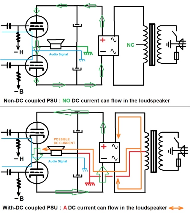
No, because the DC current of the supply cannot pass through the filtering capacitors, since their GND point is floating vs the symetric PSU of the 6080. It's what I indicate on the upper schem below :
A+!
Like you did it, 0,6mA pro triode with anode 100V the -Vg=0,9V gives 1k5/2 for two triodes= 750Ω.What I do not understand is that I had to reduce the Rk of the 1st stage from 750R to 560R to lower distortion... But it's somewhat empiric since I worked with the triangle wave linearity only.
And conversely, you increase it. 😕
If you have to go down to 560Ω I suspect the tube is weak, must have less -Vg.But with a -Vg less then 1V grid current get started.If you test with a tonegenerator with very low output impedance that's no problem.
With less current more -Vg is possible.I opted for 0,5mA for one triode with -1,1V (1,1/0,5=2k2).With two triodes parallel 2x 0,25mA (same current as with one) with -1,35V is 1,35/0,5=2k7.
The ECC83 is ment for small signal-low current applications, is very happy with 0,25mA.
No, I don't like simulations, pencil paper and datasheets.Did you made a simulation like Brice to define them ?
And building something is the past.I'm old and in a home.
Mona
No, because the DC current of the supply cannot pass through the filtering capacitors, since their GND point is floating vs the symetric PSU of the 6080. It's what I indicate on the upper schem below :
A+!
Now I am even more confused. In you previous post you wrote that all GND symbols are the same GND (chassis). This means the point between the two PSU capacitors is connected to the chassis (the green GND symbol), and hence the speaker is connected to the chassis. Sure, the caps will not pass any DC, but the chassis GND will happily provide a path for DC current.
Like you did it, 0,6mA pro triode with anode 100V the -Vg=0,9V gives 1k5/2 for two triodes= 750Ω.
If you have to go down to 560Ω I suspect the tube is weak, must have less -Vg.But with a -Vg less then 1V grid current get started.If you test with a tonegenerator with very low output impedance that's no problem.
With less current more -Vg is possible.I opted for 0,5mA for one triode with -1,1V (1,1/0,5=2k2).With two triodes parallel 2x 0,25mA (same current as with one) with -1,35V is 1,35/0,5=2k7.
The ECC83 is ment for small signal-low current applications, is very happy with 0,25mA.No, I don't like simulations, pencil paper and datasheets.
And building something is the past.I'm old and in a home.
Mona
Thanks @Ketje - I see. 😎
I will have to check all this, that's true... It reminds me now that I made the same mistake in 1993 when I worked the setup of my big OTL amps ! 🙁
Wait and See... 😉
A+!
Now I am even more confused. In you previous post you wrote that all GND symbols are the same GND (chassis). This means the point between the two PSU capacitors is connected to the chassis (the green GND symbol), and hence the speaker is connected to the chassis. Sure, the caps will not pass any DC, but the chassis GND will happily provide a path for DC current.
And where would go this DC current then ? 😕
A+!
If one tube shorts, the current will go through the resistor around that big cap, top or bottom depending of if it's a lower or upper tube going bezerk.
I see 16 mA due to the 22K resistor.
I see 16 mA due to the 22K resistor.
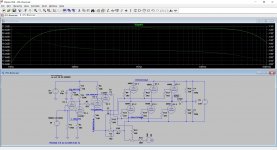
Thanks @Brice : I could see your last simulation picture, which includes @Ketje suggestions.
Tomorrow, first I'll retrace my current circuit schem with the exact values as is, and then I'll shift to this new circuit to check if there's an improvement in linearity 🙂 - since unfortunately my THD and spectrum analysis is off now 🙁.
And of course, I"ll re-check my preamp tubes... 🙄
Wait and See... 😉
A+!
If one tube shorts, the current will go through the resistor around that big cap, top or bottom depending of if it's a lower or upper tube going bezerk.
I see 16 mA due to the 22K resistor.
True, yes, but 16mA on a DCR of 5R6 (usual DCR of a 8R speaker) represents 5.6*0.016² = 0.00143W and 5.6*0.016 = 0.089VDC, which is not dangerous for the speaker.
There's no other possible path since the power supply of the output stage has no common point with the chassis, conversely to what is shown on my lower PSU drawing.
If the PT winding common point (CT) was connected to the chassis, then yes, much more current (even the PSU short-circuit current) would flow into the speaker and burn the moving coil.
I saw this issue on a Peavey PA head which blew one of her 2N3055 output transistors... Along with the speaker connected. 😡
On my previous OTL, I had 4x6080 paralleled : two at the upper side, two at the lower side (that said 8 triode sections total). This allowed me to remove one 6080 (2 triode sections) and so create an imbalance of 1x6080 upper and 2x6080 lower (or conversely).
I made the test : nothing occured in the speakers, except a light 100Hz buzz because of the imbalance of the upper and lower voltages.
Many people think that OTL circuits are dangerous for speakers. Yes, some are, but not all...
A+!
Last edited:
Yes I agree.
16 mA when a tube shorts is not dangerous to the woofer (as mid/tweeter have caps in the cross over) and really acceptable.
And if by any bad luck 2 tubes shorts in the same event, one on top and one on bottom, then a fuse in the +/-115V should prevent further PS damage.
16 mA when a tube shorts is not dangerous to the woofer (as mid/tweeter have caps in the cross over) and really acceptable.
And if by any bad luck 2 tubes shorts in the same event, one on top and one on bottom, then a fuse in the +/-115V should prevent further PS damage.
Ok, I just realised you left the center tap of the transformer unconnected.And where would go this DC current then ? 😕
A+!
However, according to the schematic in the magazine article posted earlier, the centre tap should be connected to GND. Without this GND reference, the floating PSU potential will just follow the audio AC signal applied to the power tubes. There will be essentially no audio signal across the speaker.
Yes I agree.
16 mA when a tube shorts is not dangerous to the woofer (as mid/tweeter have caps in the cross over) and really acceptable.
And if by any bad luck 2 tubes shorts in the same event, one on top and one on bottom, then a fuse in the +/-115V should prevent further PS damage.
Yes. It's what I'll do on a definitive build : one fuse in the +115, one in the -115, just before the 6080.
A+!
- Home
- Amplifiers
- Tubes / Valves
- The ultimate OTL6080