Scratch that: To overcome the ringing on a 1kHz square wave the capacitor is so large that HF response is down a good 6db.
Since I've used these OPTs I feel it's due to the 124B phase splitter.
Since I've used these OPTs I feel it's due to the 124B phase splitter.
No room for more tubes in the chassis. I'd have to use an AD712 opamp, but I don't really know how to do it with a single ended 12V supply. I might see if I can fit toroids inside instead of the 124B.
No need for another socket-

If you need more gain swap it so that the 6n6p stays as a cathodyne on it's own socket, and run a 6n1p or 6n2p on it's own socket as the voltage amp stage.
That's what I would do at least...
If you need more gain swap it so that the 6n6p stays as a cathodyne on it's own socket, and run a 6n1p or 6n2p on it's own socket as the voltage amp stage.
That's what I would do at least...
Oh, and for single supply operation of opamps that don't require much current you can use either a resistor divider virtual ground like in the cmoy pocket amps, or use a cheap rail splitter chip like the TLE2426, I used to use them a bunch back when I messed around with headphone amps and signal processing type of projects. TO92 package so they are tiny enough to fit anywhere or even "dead bug" wire them on an IC socket...
Cheers man. But will that cathodyne have enough grunt to drive 47k and 4 6P1P triodes? I was thinking I'd need a buffer on the phase splitter like the Williamson KT88.
Last edited:
I think it should be fine, but I suppose it wouldn't hurt to up it to 100k in this application. Since you are CCS biased there's very little chance of runaway, and 4x parallel tubes using 1/4 of the max grid resistance of 500k would be 125k, so you would still be within spec.
Could always use a TO220 mosfet for the cathodyne device, slap a heatsink on it, and run it nice and high current, it would work pretty good too. But that's a bit too much heresy for some to handle... I like the idea but can never bring myself to actually do it!
What's your cathode voltage, anyway? Something like 20~25? It shouldn't take much signal to drive those triode connected anyway, assuming 25 volts across 47k (and the grid capacitance) you're looking at only a bit over half a mA anyway, so I wouldn't worry really all that much, but building up from scratch I would pencil in 100k grid resistance.
Last edited:
It was 47k for the loading of the 124B. It still is, and without gNFB the square wave is MUCH better. Anyone wanna buy a pair of Hammond 124B? LOL
There isn't enough gain for a gNFB loop now, but if I can find space for one more tube socket... 🙂
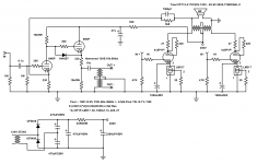
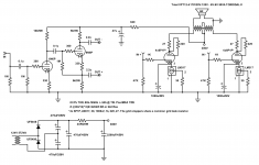
I modified it a little from your idea, here's the current schematic:
There isn't enough gain for a gNFB loop now, but if I can find space for one more tube socket... 🙂
I modified it a little from your idea, here's the current schematic:
Attachments
Looks good!
If you want a smidge more gain throw an LED under that first triode, should work about the same as bypassing the resistor with a nice cap. Maybe even throw a CCS on the plate, or swap that first triode out for a 6n2p, but that's all up to what you want to do. Triode outputs don't always need much feedback, but I like to run it when feasible.
If you want a smidge more gain throw an LED under that first triode, should work about the same as bypassing the resistor with a nice cap. Maybe even throw a CCS on the plate, or swap that first triode out for a 6n2p, but that's all up to what you want to do. Triode outputs don't always need much feedback, but I like to run it when feasible.
The first triode is biased at ~4.7V so two LEDs in series... Or a battery in series with the input for that matter. 4.5V is easy to find. Without gNFB there is enough gain though... Ya I thought about using a CCS plate load, too. Like a DN2540 perhaps but for now it's good as is.

I'm strongly considering a four channel push pull with these for my car, but may be using the 12AV5GA for that with crazydrive instead.
I was thinking of looking into totem pole stages... I have a few speakers coming in for another Karlsonator build that use two 16 ohm drivers each, so it can be wired up for either 8 or 32 ohm load. I've also got a bunch of film caps that might work in parallel for coupling to the speakers, and DC protection/dethumper relays are easy to set up. Isn't it tricky to get totem pole stages to do low THD?
I was thinking of looking into totem pole stages... I have a few speakers coming in for another Karlsonator build that use two 16 ohm drivers each, so it can be wired up for either 8 or 32 ohm load. I've also got a bunch of film caps that might work in parallel for coupling to the speakers, and DC protection/dethumper relays are easy to set up. Isn't it tricky to get totem pole stages to do low THD?
I mean like this:
BTW these 6P43P will drop right into the circuit of the Stupendous. You could even tetrode connect the tubes to get more power.
BTW these 6P43P will drop right into the circuit of the Stupendous. You could even tetrode connect the tubes to get more power.
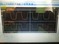
I just scoped the output at 10kHz... This is what open loop triode with 640ma total plate current looks like driving a 50va toroidal power tranny 🙂
Not bad if I don't say so myself!
Not bad if I don't say so myself!
Attachments
Curious to see how it looks with some global negative feedback. Either way it's pretty good.
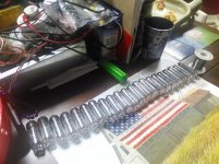
I got my toroids and chassis for the 6P43P-E build, 2x50VA-5V/5V to show a ~4100:8 load (series connected secondaries) and a 100VA 230V power toroid. Also got a quad of RCA "made in great Britain" EL86 for a song to run and compare to the Russians. Just figuring out if I want to go fixed bias, garter bias, or some sort of bias servo or current mirror, but currently I'm leaning towards garter bias.
I got my toroids and chassis for the 6P43P-E build, 2x50VA-5V/5V to show a ~4100:8 load (series connected secondaries) and a 100VA 230V power toroid. Also got a quad of RCA "made in great Britain" EL86 for a song to run and compare to the Russians. Just figuring out if I want to go fixed bias, garter bias, or some sort of bias servo or current mirror, but currently I'm leaning towards garter bias.
Nah, I'm not a CCS guy for output stages. It restricts you to class A unless you do some sort of state-variable bias current witchcraft.
I'm leaning towards garter bias the most, 315 volts supply, 20+20 volts across 390R cathode resistors, mosfet screen supply (adjustable from 100-250 volts) sounds like it will work nicely.
I was also considering fixed bias with mosfet source followers directly coupled to the output grids, AB2 should be killer with these tubes... I figure a couple fets isn't that much more work if building up a bias supply anyway. Needs more room in the soon-to-be cramped chassis though.
Either way, it's going to be 6N2P concertina splitter, same front end as I did on the flea amplifier, just with more gain. Mosfet filter for the front end for ~285-295 volts or so, a little global negative feedback. With ~275 volts (assuming garter bias) across the output tubes and a 4100 ohm load I should get pretty respectable linearity and power, even before feedback.
I was considering going differential feedback with a LTP front end and grounding the center of the series connected secondaries, but for whatever reason I just like concertina splitter types better, so I'll go with my "usual" topology.
- Home
- Amplifiers
- Tubes / Valves
- The "Stupendous" 6P1P 4PP amplifier!