Ok, a new day with a fresh mind.
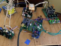
I started by testing the Toroidy transfomer first, all secondaries disconnected from the SLB:
Soooo, this means there's nothing really broken in the power supply, as it works fine. This is good news, sort of. However, why did it act up so badly yesterday? I hate when I can't reproduce the issue. Where would you guys look?
I started by testing the Toroidy transfomer first, all secondaries disconnected from the SLB:
- DC resistance of all secondardies is less than what my DVM will measure (0.0 Ohm). Not unreasonable, since this is a high-power transformer.
- DC resistance between the secondaries is "overload", which sounds good, too.
- Brought up the transformer via Variac and bulb tester (can't afford blowing more fuses, because I must not run out of fuses on a weekend 😉). Bulb tester remains dark. All secondardies work fine, and give the same AC readings. Good, too.
- Brought up the transformer without Variac and bulb tester. AC readings on the secondaries are fine (approx. 22 VAC). Good.
Soooo, this means there's nothing really broken in the power supply, as it works fine. This is good news, sort of. However, why did it act up so badly yesterday? I hate when I can't reproduce the issue. Where would you guys look?
@mbrennwa
My post and XRK971’s post had pretty much all the specifics. In particular, please make 100% sure that the Molex connector with the wires in it, aren’t jarred loose for some reason. They should be tight. If there is doubt, I would go ahead and directly solder although this might be too onerous with your jigsaw 3D puzzle of a build! Beautiful build though!
I don’t know what value fuses you are using, but they might be a tad small to deal with the inrush current. Usually I use Toroid VA/Mains V X 1.0 to 1.5. Your mains voltage I believe is 230-240V. But have you measured it with a multimeter? It’s probably a good idea to do so and to look at the variance in the mains voltage over the day. Here in the USA, my mains runs a little higher, about 122-123 volts instead of the standard 120V.
Sometimes you need a fudge factor that is closer to the 1.5 mark to deal with the inrush current (I use 1.25 personally unless I am using a special inrush current limiter circuit where you don’t need as much of a fudge factor).
Your build is unique and compact, I don’t know if you have space for a fancy inrush limiter w/relay, etc….like XRK’s Soft as a Feather Pillow, but you should have space for at least one NTC Thermistor like they use on the various Pass projects. If you only have a single primary with your Toroidy (for 240V), you can solder in an NTC Thermistor to the ‘hot’ line. A CL60 type would be fine.
If the SLB isn’t the issue, and the Toroid works as advertised, then all you have left is a stray ground connection (which you can check with a multimeter) and higher inrush currents. I’d use some forced air and make sure everything is nice and clean in case stray wires were hanging around after the build. Gremlins and all…
Best,
Anand.
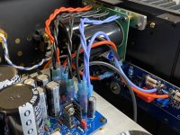
Good news that it checks out. Is there deterioration between the high power pass transistor (2SC5200) insulation and heatsink? A small burr or pinhole on silicone could cause a dead short that would blow a fuse instantly. Check for short to ground on all BJT tabs.

How/where would you check for a stray ground connection? I don't quite understand what you mean by this.... all you have left is a stray ground connection (which you can check with a multimeter) and higher inrush currents.
II already checked the Molex and transistor Isolation from the chassis. All good.
@mbrennwa
I clip my black lead of my DMM to the chassis ground of the amplifier. Then I take my red lead of my DMM while observing all relevant schematics and make sure that areas that should be connected to ground really are and areas that shouldn’t be are not. I also look for stray wires which can occur in any build depending on the fastidiousness of the diy’er. With your 3D build, only you would know. But if you built it to perfection, then you have done good.
For example, V+ and V- on the main amp boards should never be connected to ground. You probably checked for all that, and since the amp powers up (but it did so with a variac), it makes me think that high inrush current may be what it was after all.
Best,
Anand.
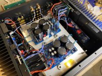
Ok, she's back alive. I can't really tell what the issue was, but it's gone (at least for now). I did put in the thermistor to avoid the inrush peak for good measure, but my gut feeling says that this was not the problem. I hope the gremlin fell out while the chassis was open...
Fantastic news Mbrennwa! Your back in action.

Those darn Gremlins.....He must have scooted across the Globe and made a new home in my DAC!
Those darn Gremlins.....He must have scooted across the Globe and made a new home in my DAC!
Your build hadn't employed an inrush limiter until now, then?I did put in the thermistor to avoid the inrush peak for good measure, but...
Fuses can and will deteriorate over time; operating near their limits will hasten that process.
Attachments
Randomly, when I turn on the MacMini music server it doesn’t play friendly with the JLSounds usb converter.
Today was one of those random days🙄
Today was one of those random days🙄
Finally getting around to building, so I can use the spare Mundorf Myltic 22,000uf I have lying around as they're rated to 6A ripple current. But is it worth me using them here? Any audible benefit given the circuits performance?I have a pair of DR white solder mask with ENIG boards.
Is this still the latest / matching BOM?
I'd like to avoid CDE/Panasonic caps - the larger caps (C7,8,13,14) are easier to substitute (Mundorfs will fit), but what are the best options for C15/16/17 &19 and the two smaller C21/22?
I presume it's just a case of stuffing, slowly add power and hope nothing gets fried?
Where's the schematic for stuffing?
I would be extremely surprised if you could hear a difference in the sound coming out of your speakers when using the Mlytics in the SLB instead of the ones specified in the BOM.
Nah, I couldn’t tell a difference from using different caps in this location.
Save those pricey caps for a different job🤣
Save those pricey caps for a different job🤣
Mbrennwa and Vunce are correct. Those caps only serve to smooth the rectified ripple down to 125mV or so and SLB pass transistor takes care of the rest of the ripple. You also don’t want it to be too large as that increases the charging peak currents required per cycle and cap heating may increase. The 15,000uF value has been optimized based on simulation in LTSpice for 5A load.
Depending on your amp, you could try using them at the output of the SLB to see if you notice any benefit.
- Home
- Group Buys
- The SLB (Smooth Like Butter) Active Rect/CRC/Cap Mx Class A Power Supply GB