Good idea - in the meantime, making a small adapter might be the way to go.

I have two single rail SLBs. My plans changed slightly with their use. I have a few questions.
Can I use two of them together to make a dual rail unit SLB?
What is the Max single rail voltage that I could use the SLB for?
Could a dual SLB be used to only supply the positive rail in an F3 and can both secondaries on the transformer be wired together to sum the transformer voltage (so two 22V secondaries getting 46 to 48V DC out of the SLB)?
Just trying to see the best way to utilize what I have and to make the Power supplies modular as much as I can.
Sorry, you cannot make a dual rail by putting two single rail in series. It’s like you cannot make a dual rail regulator using two 78xx regulators but new a 78xx for positive rail and 79xx for negative rail.
The main pass transistor is just the wrong gender. It needs to reference to GND.
The main pass transistor is just the wrong gender. It needs to reference to GND.
Two 22v secondaries in series is 44v x 1.4 is 62vdc no load. 3v drop due to SLB and 2-5v drop due to sag under load. So 5v to 8v drop from 62v or 55 to 57vdc under load.
Max voltage is limited by LT3420 and that’s 70vdc. Make sure your caps can handle that. So 50v ac secondaries are the limit for the SLB.
Max voltage is limited by LT3420 and that’s 70vdc. Make sure your caps can handle that. So 50v ac secondaries are the limit for the SLB.
Can this psu be used for a class AB amp like the Wolverine or would your all-cee psu be a better choice if the voltage is lower than 70V DC? It mentions in the description that it is a Class A psu. I was planning to share the PSU with multiple different amps mostly class A, but also the Wolverine also. Will have to get 80V caps.
X,
What makes this a PSU for a Class A amplifier and the All Cee PSU for a Class AB amplifier? To a relative novice they look like they do the same thing, so what makes them better for one type of amplifier or another? They both take a transformer AC secondary voltage and convert it to DC voltage.
What makes this a PSU for a Class A amplifier and the All Cee PSU for a Class AB amplifier? To a relative novice they look like they do the same thing, so what makes them better for one type of amplifier or another? They both take a transformer AC secondary voltage and convert it to DC voltage.
The SLB has a capacitance multiplier circuit (actively removes supply ripple from a CRC) for very clean low ripple power. This is needed as many Class A amps don’t have as good power supply rejection ratio (PSRR) and are prone to making the mains hum leftover in the ripple of the supply. Also, large currents flow continuously and this generates a lot of heat in the bridge rectifier. So an active bridge is used (LT4320 and 4 low RDson MOSFETs) to reduce heat, reduce voltage dropout, and have almost no diode switching noise. Even at 5A continuous draw, ripple is under a few mV rms.X,
What makes this a PSU for a Class A amplifier and the All Cee PSU for a Class AB amplifier? To a relative novice they look like they do the same thing, so what makes them better for one type of amplifier or another? They both take a transformer AC secondary voltage and convert it to DC voltage.
The All Cee’s is a simple diode bridge rectifier and CC or CRC capacitor smoothing bulk rail cap PSU. It is used for Class AB amps because they tend to have push pull (complementary output) stages that have higher PSRR and don’t need such a clean PSU. If you drew 5A continuously from a CRC similarly sized as SLB, ripple would be in the hundred to two hundred mV range.
Since Class AB normally doesn’t draw a lot of current except when playing high levels or high dynamic peaks, a plain CC or “All Cee’s” bank is fine and gives added advantage of larger reserve for big dynamic peaks like bass transients.
The SLB is a lot more complex and expensive. But for some single ended (SE) Class A amps, it turns an amp with audible hum to a silent and wonderful amp that you cannot tell is turned on with ear pressed to speaker cone.
You could use SLB on Class AB but I would add larger downstream cap bank to give more reserve for dynamic peaks.
So hope that helps.
What is the maximum wattage rating suggested for this PSU in class A amp? Using A/B amp?
Is there possible to regulate output VDC? What is the maximum input voltage?
What are the PSRR numbers for this PSU?
If it is needed to use bigger caps then is there a room for that?
Also soft start would be nice. 🙂
Is there possible to regulate output VDC? What is the maximum input voltage?
What are the PSRR numbers for this PSU?
If it is needed to use bigger caps then is there a room for that?
Also soft start would be nice. 🙂
In Class A the SLB was designed for up to 5A continuous flow. Max voltage is 70V limited by 7420 active bridge. Let’s say max DC Voltage after 3v drop is 67V x 2 rails x 5A is 670W total power delivered. Assuming 33% max efficiency for Class A amp it’s probably capable of supporting a 200W per channel Class A amp. In Class AB max current will be limiting factor. But dynamic peaks can be helped by. Larger cap bank downstream.
No it is not regulated. Only smoothed and ripple reduction is about -50dB.
There is a Soft Start using solid state relays designed by Jhofland. Look for SFP soft start thread. Also available in my shop.
No it is not regulated. Only smoothed and ripple reduction is about -50dB.
There is a Soft Start using solid state relays designed by Jhofland. Look for SFP soft start thread. Also available in my shop.
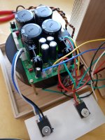
I am building this power supply in a separate chassis for FirstWatt M2X amp (and for other Class A Firstwatt amps).
220VAC -> switch -> fuse -> NTC 8D-20 -> primary of toroidal transformer (primary 220-0, dual secondary 21-0-0-21) -> SLB
I have two question.
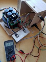
Before putting these in a chassis, I got +/-27.2VDC from this SLB without NTC 8D-20 and load.
I put these all in a chassis at this time, and power it up .. then I smell somthing burnning so power off immediately.
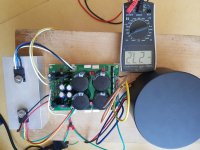
I opened the chassis for checking some wirings and power it up again, but this time I got +27.6VDC at both PVout and NVout.
It seems so weried. I don't know what happened.
Is it okay to just use this as it is?
I turn the offset RV to CCW fully, and get 27.2VDC with no load.
It seems so high for a FirstWatt M2X amp that accepts around 24VDC.
Are there ways that drop some more output voltage of this power supply proper for M2X amp?
220VAC -> switch -> fuse -> NTC 8D-20 -> primary of toroidal transformer (primary 220-0, dual secondary 21-0-0-21) -> SLB
I have two question.
Before putting these in a chassis, I got +/-27.2VDC from this SLB without NTC 8D-20 and load.
I put these all in a chassis at this time, and power it up .. then I smell somthing burnning so power off immediately.
I opened the chassis for checking some wirings and power it up again, but this time I got +27.6VDC at both PVout and NVout.
It seems so weried. I don't know what happened.
Is it okay to just use this as it is?
I turn the offset RV to CCW fully, and get 27.2VDC with no load.
It seems so high for a FirstWatt M2X amp that accepts around 24VDC.
Are there ways that drop some more output voltage of this power supply proper for M2X amp?
Attachments
@namghiwook
Your voltage of ~27VDC is just fine. I am concerned about the burning smell. Any sign of where that may have come from?
Your voltage of ~27VDC is just fine. I am concerned about the burning smell. Any sign of where that may have come from?
Last edited:
On your DMM, I see both a “27.6 Vdc” and a “- 27.2V dc” so I think you are fine. Make sure you have the correct polarities connected on your DMM (positive to red, negative to black/gnd). Or else you will be confused about the polarities when you look at the DMM display. Don’t fool yourself!
You have to understand that these values are near normal when you do not have a load. The load on an M2X is 1.3A approximately, so the voltage will/should drop to about +/-24 to +/- 25V. Even +/- 27Vdc is fine for an M2X design as the JFETs in the input stage (if using the Ishikawa Board) will not exceed their dissipation at that voltage.
Make sure all your wiring to that external umbilical connector is absolutely perfect. Use 2 DMM’s if you need to. And use a variac or dim bulb tester. I like to use variacs.
Remember the M2X circuit takes up to 60 seconds to draw a load as the 3300uf capacitor has to charge up first. The optical bias circuit on the M2 is a pretty cool implementation by N.Pass.
Best,
Anand.
Last edited:
namghiwook,
I believe all your questions have been asked many times in this thread and been answered.
Most recent posts #1481, 1484, 1491
Your wooden enclosure looks a bit small to safely hold the SLB with transformer 😬
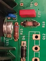
Check R18, looks like it was overheated, could be the source of the smell.
I believe all your questions have been asked many times in this thread and been answered.
Most recent posts #1481, 1484, 1491
Your wooden enclosure looks a bit small to safely hold the SLB with transformer 😬
Check R18, looks like it was overheated, could be the source of the smell.
Yes, sharp eye Vunce.
Hi namghiwook,
R18 will try to pass the full current of the big Q12 external transistor if the transistor is disconnected or open circuit. If this happens, it will smoke and burn. I had this happen once when I forgot to plug the Molex MiniFit connector in before powering up.

Was your Q12 plugged in? Did you check to make sure the pin outs on Q12 cable matches the pins on the board?
27v under no load is good. You will have about 3v drop and this will make it 24v so perfect for 1st Watt 25W Class A amps.
I agree with Vunce that a small wood box with no air space is not the best choice for a chassis for this PSU. Add some vent slots. Also, know that the white KOA BPR resistors can reach 150C and they might burn the wood if they touch.
Hi namghiwook,
R18 will try to pass the full current of the big Q12 external transistor if the transistor is disconnected or open circuit. If this happens, it will smoke and burn. I had this happen once when I forgot to plug the Molex MiniFit connector in before powering up.
Was your Q12 plugged in? Did you check to make sure the pin outs on Q12 cable matches the pins on the board?
27v under no load is good. You will have about 3v drop and this will make it 24v so perfect for 1st Watt 25W Class A amps.
I agree with Vunce that a small wood box with no air space is not the best choice for a chassis for this PSU. Add some vent slots. Also, know that the white KOA BPR resistors can reach 150C and they might burn the wood if they touch.


Give it a try and monitor the temps .
The drilled holes are good. Maybe some more drilled holes on top and bottom to allow air to enter and leave easily.
The drilled holes are good. Maybe some more drilled holes on top and bottom to allow air to enter and leave easily.
- Home
- Group Buys
- The SLB (Smooth Like Butter) Active Rect/CRC/Cap Mx Class A Power Supply GB