Or you could just use the active bridge designed for the SLB and avoid ringing altogether since the mosfet switches at zero crossing. No ringing possible.
Are you looking to use the SLB in a high voltage tube application?I want to build an hifi tube amp with a push pull of kt88. The only problem I face is creating an alternative to the LT module.
So i want to replace it with fast diodes, do you have any recomendation? Also should i use capacitors in paralelle with diodes, or is it just slowing down the recovery time, creating another form of noise (noise from slow diodes) ?
Thank you.
Line1 : Soft recovery diodes lower transformer ringing by 20 times.Write the title of the Linear Audio article, on line #1 of a new and empty text file
Leave line #2 of the text file blank
Write the last sentence (the fourth sentence) of the "Summary" section of the Linear Audio article, on line #3 of the text file
Now read the text file. Aha, eureka.
Line2 :
Line3 : (I don't have the article).
Anyway thank you Mark, i know you can't just give freely what is supposed to be paid. So no hard feelings 😉
Yes I think I will just replace the module with diodes, probably soft recovery diodes.Are you looking to use the SLB in a high voltage tube application?
This is exactly what I want to achieve, a zero crossing style switching (with similar noise) but with diodes.Or you could just use the active bridge designed for the SLB and avoid ringing altogether since the mosfet switches at zero crossing. No ringing possible.
I bought the paper but am finding that many of the top rated diodes are either out of stock or custom orders only minimum 3000 quantity. 🙄 Good paper though nonetheless worth every penny of $3.56.
Last edited:
According to tvicol it don't work, he told me so in this post :
https://www.diyaudio.com/community/threads/ideal-bridge-rectifier-gb.333844/page-22#post-6744581
https://www.diyaudio.com/community/threads/ideal-bridge-rectifier-gb.333844/page-22#post-6744581
After performing the assignment in post #1320 above, and saying Eureka ...
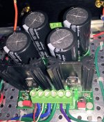
I just buy the lowest Vfwd rectifiers I can find. Usually they are "FERD" (not hexfred) -- Field Effect Rectifier Diodes -- from ST Microelectronics, in the THREE PIN package. Or else I buy the MBR series of Schottkys. MBR10100 is personal a favorite for Chip Amps. You can read its part number in the picture below.
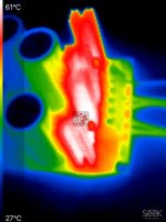
Why "lowest Vfwd"? Because diode power dissipation equals voltage times current. Therefore low Vfwd means minimum heat, and minimum heat means maximum lifetime for the nearby electrolytic capacitors that can easily get cooked.
_
Attachments
R3-R6 (KOA Speer Part # BPR58CR10J) is out of stock everywhere. Looks like 2 of these get put in series on each rail to make a 0R2 resistor in the CRC.
I'm looking at substitutes on Mouser. What is the total wattage rating per rail required for these? And can I use wirewound resistors, or any type of resistor? Or does it have to be a current sense resistor?
I'm looking at substitutes on Mouser. What is the total wattage rating per rail required for these? And can I use wirewound resistors, or any type of resistor? Or does it have to be a current sense resistor?
Any 5W will do here. It’s for a CRC so no need to use koa BPRs. Vishay green 3W ceramic axial soldered like a fence. I did that before to increase dissipation power.

Thanks for the video. I looked at the sound file on Audacity and I suppose this might be similar to what an O-scope will see. The FFT says that the pulses have about a 390Hz frequency, they are spaced at about 4.7Hz an have an exponential rise and decay envelope. Not an high impulse followed by a decay.


The 4.7Hz sounds like a frequency that might match the time constant of the BA3 input stage coupling caps and input resistor. Could it be that you have DC somewhere that is charging the caps, and at some point, the charge is released?
Is there a discharge bleeder resistor on your input cap? If you ground your RCA inputs does the sound still remain?
I suspect that this is not a PSU problem but something in the amp input stage.
Fascinating information XRK, I appreciate the effort. I did for awhile have 1v of DC before the FE output cap but I have since zeroed that offset and the sound remains in both channels. The sound also remains when I plug in a preamp that is grounded and the noise floor does not change...meaning no additional hums or buzzes or static appears. There is no input cap in this design and there are 3 resistors to ground on the FE board per side.
BA3 Article
I linked the BA-3 article from Firstwatt here if you wanted to see the schematic of the system. I also posted similar info as well as additional thoughts based on your tests on the BA3 forum page.
BA3 Article
I linked the BA-3 article from Firstwatt here if you wanted to see the schematic of the system. I also posted similar info as well as additional thoughts based on your tests on the BA3 forum page.
I understood now and i am saying eureka 😉 And it makes sense now to choose lowest Vf diodes 😉After performing the assignment in post #1320 above, and saying Eureka ...
I just buy the lowest Vfwd rectifiers I can find. Usually they are "FERD" (not hexfred) -- Field Effect Rectifier Diodes -- from ST Microelectronics, in the THREE PIN package. Or else I buy the MBR series of Schottkys. MBR10100 is personal a favorite for Chip Amps. You can read its part number in the picture below.
Why "lowest Vfwd"? Because diode power dissipation equals voltage times current. Therefore low Vfwd means minimum heat, and minimum heat means maximum lifetime for the nearby electrolytic capacitors that can easily get cooked.
_
Thank you Mark, I will just bother you one last time... is ringing the only form of noise in a bridge rectifier ? does leaked current create noise, or is it just linked to ringing too ?
I am still working on my tapping/pulsing noise problem. When I have my FE and output stage fully biased, I am still getting too high voltage from the SLB. I was aiming for 32v and get +34v, sometimes 36v. I don't recall if there was enough adjustment range to account for that. Is there something else I can do?
If your using an Antek 28v trafo your not going to get below 34vdc when loaded.
28 x 1.41 = 39.5 - 5v(Capmx/sag)=34.5vdc
Also, the Anteks seem to run a little bit over voltage so your 28V secondary might be really 28.8V which will account for even more than the 34.5 V output.
There is not enough adjustment to “trim off” excess voltage.
28 x 1.41 = 39.5 - 5v(Capmx/sag)=34.5vdc
Also, the Anteks seem to run a little bit over voltage so your 28V secondary might be really 28.8V which will account for even more than the 34.5 V output.
There is not enough adjustment to “trim off” excess voltage.
Yup, that definitely seems to be the case - I was planning/expecting more sag from the Anteks but it is as you say. Is there a part I can change on the SLBs to lower the output voltage? Could I change the Bourne variable resistors to give more range for example? Or should I just run the whole amp at 34 volts and live with the potentially shortened lifespan of the JFets?
Changing the trim pots won’t affect the range of adjustment. JFETs? SLB uses MOSFETs for the active rectifier and BJTs for the cap Mx pass transistor.
Hello all, I'm using my SLB duel rail in a 12V Hirage Le Monstre stereo amp. Both amp boards together seem to draw about 2.3 Amps at +/- 12.05V. The concern/ problem that I have is that I can only get a max value of 1.65V across the BJT on the negative rail. I've adjusted the positive rail to match, but it's not the expected 3V.
Any suggestions?
Thanks
Any suggestions?
Thanks
I have never run it at such a low voltage. It might be that the drop of 1.65v is the max for 12v. 3v is for 24v and above rails. One thing to check is the ripple you get out of cap Mx. if it’s very low already then 3v drop was not needed and you bought yourself a few more watts of amp output for free.
- Home
- Group Buys
- The SLB (Smooth Like Butter) Active Rect/CRC/Cap Mx Class A Power Supply GB

