The voltage drop is typically 3v through the pass (slave) transistor on the CFP. All 25w Nelson Pass Class A amps are designed around 1.25A quiescent bias current and +/-24v rails. The dissipation in the pass transistors is then 3v x 1.25A per rail per channel or 3.75w per rail per channel. x 2 rails x 2 channels is 4x3.75w total =15w. I think the front aluminum faceplate can easily dissipate 15w (or 7.5w ea).
Or get a small heatsink like this one (150mm x 60mm x 25mm) for $4 - it works fine:
Aluminum Heatsink Cooling Fin 150mmx60mmx25mm for Power Amplifier A6P7 190268295864 | eBay
I am using with an M2 right now (same category of 25w Class A Nelson Pass amp), and it works well to provide the current needed.
Last edited:
49C is not too hot for heatsinks. Normal operating temp for typical Class A heatsinks are 50C to 55C.
GB Status update...
I am asking for your help here to update the list if I forgot to add you here. I get a lot of requests via PM for a GB, and the way it should work is to start at the list and then a PM, rather than other way around. I can't easily keep track of it from the PM back to the list.
Here is what I have so far, and I know some are missing here:
baswamin - 2 boards - Paid
meanie - 2 boards - Paid
jwjarch - 2 boards - Paid
gary s - 2 boards - Paid
nautibuoy - 2 SLB boards - 2 SLB-SR boards - both Paid, ship together
antoniopf1972 - 2 boards - Paid
ravid - 2 boards - Paid, Simple PSU Paid, ship at same time
Gricko - 2 boards - Paid
poseidonsvoice - 2 boards - Paid
Bkdog - 2 boards - Paid
Jazzfan - 4 boards - Paid
yoaudio - 2 boards - Paid
van of monks - 1 board - Paid
Wtl - 4 boards - Paid
cerole - 2 boards - Paid
s610adam - 4 SLB - 6 SLB-SR - Paid
pbergstrom - 2 boards - Paid
ferret - 2 boards - Paid
Roundtoit - 2 SLB boards, 2 SLB-SR boards - Paid
Tubesguy - 1 SLB board - Paid
Kokanee - 8 boards - Paid
Arthur - 10 boards - Paid
potepuh - 2 SLB boards - Paid
TboneAK - 2 SLB Boards - Paid
Sanjeevm - 2 SLB Boards - Paid
Centurion53 - 1 SLB board - Paid
Vunce - 2 SLB boards, 2 SLB-SR boards - Paid
Shawnstium - 1 SLB - Paid
*Ermine22 - 4 SLB boards - Need to know if want exchange for lost previous GB
1 more board please
Hi X,
Please add one more board. For my Moth 30 project. Will do PayPal pmt in a moment.
Kevin
P.S. Please send me an inv to my PP account. Can't seem to make another payment from the previous one.
Hi X,
Please add one more board. For my Moth 30 project. Will do PayPal pmt in a moment.
Kevin
P.S. Please send me an inv to my PP account. Can't seem to make another payment from the previous one.
Last edited:
Hi X, is the Alpha BB you referred to, the Alpha 20?
I have those boards from you and that is planned with the SLB here as my ultimate power amp. I will then mate it to the Yarra as the front end.
I have those boards from you and that is planned with the SLB here as my ultimate power amp. I will then mate it to the Yarra as the front end.
Hi X, not to worry found your details and made the payment. Last question - can the LT4320 be used with a DIP connector, or is it better to solder it in directly?
Dip sockets are usually only a problem with high speed op-amps at high frequencies, so 50/60 hz shouldn’t be an issue. They can add a small amount of the capacitance between the PCB and the leads.
Thanks for the payment Ferret, I have you down for 3 boards then. You can skip the sockets if you like. It's not like we need to swap out the LT4320's.
baswamin - 2 boards - Paid
meanie - 2 boards - Paid
jwjarch - 2 boards - Paid
gary s - 2 boards - Paid
nautibuoy - 2 SLB boards - 2 SLB-SR boards - both Paid, ship together
antoniopf1972 - 2 boards - Paid
ravid - 2 boards - Paid, Simple PSU Paid, ship at same time
Gricko - 2 boards - Paid
poseidonsvoice - 2 boards - Paid
Bkdog - 2 boards - Paid
Jazzfan - 4 boards - Paid
yoaudio - 2 boards - Paid
van of monks - 1 board - Paid
Wtl - 4 boards - Paid
cerole - 2 boards - Paid
s610adam - 4 SLB - 6 SLB-SR - Paid
pbergstrom - 2 boards - Paid
ferret - *3 boards* - Paid
Roundtoit - 2 SLB boards, 2 SLB-SR boards - Paid
Tubesguy - 1 SLB board - Paid
Kokanee - 8 boards - Paid
Arthur - 10 boards - Paid
potepuh - 2 SLB boards - Paid
TboneAK - 2 SLB Boards - Paid
Sanjeevm - 2 SLB Boards - Paid
Centurion53 - 1 SLB board - Paid
Vunce - 2 SLB boards, 2 SLB-SR boards - Paid
Shawnstium - 1 SLB - Paid
*Ermine22 - 4 SLB boards - Need to know if want exchange for lost previous GB
xrk971, in thread #194 you mention the 'AlphaBB' - is this the same as the Alpha 20 which I have PCB's here from your store ready to build. I plan to use the SLB for this amp for my next ultimate power amp build, before doing an ultra extreme high end build on the Yarra preamp.
Regards,
Gary..
Regards,
Gary..

Single dual rail SLB tested with M2X amp
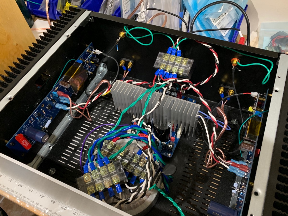
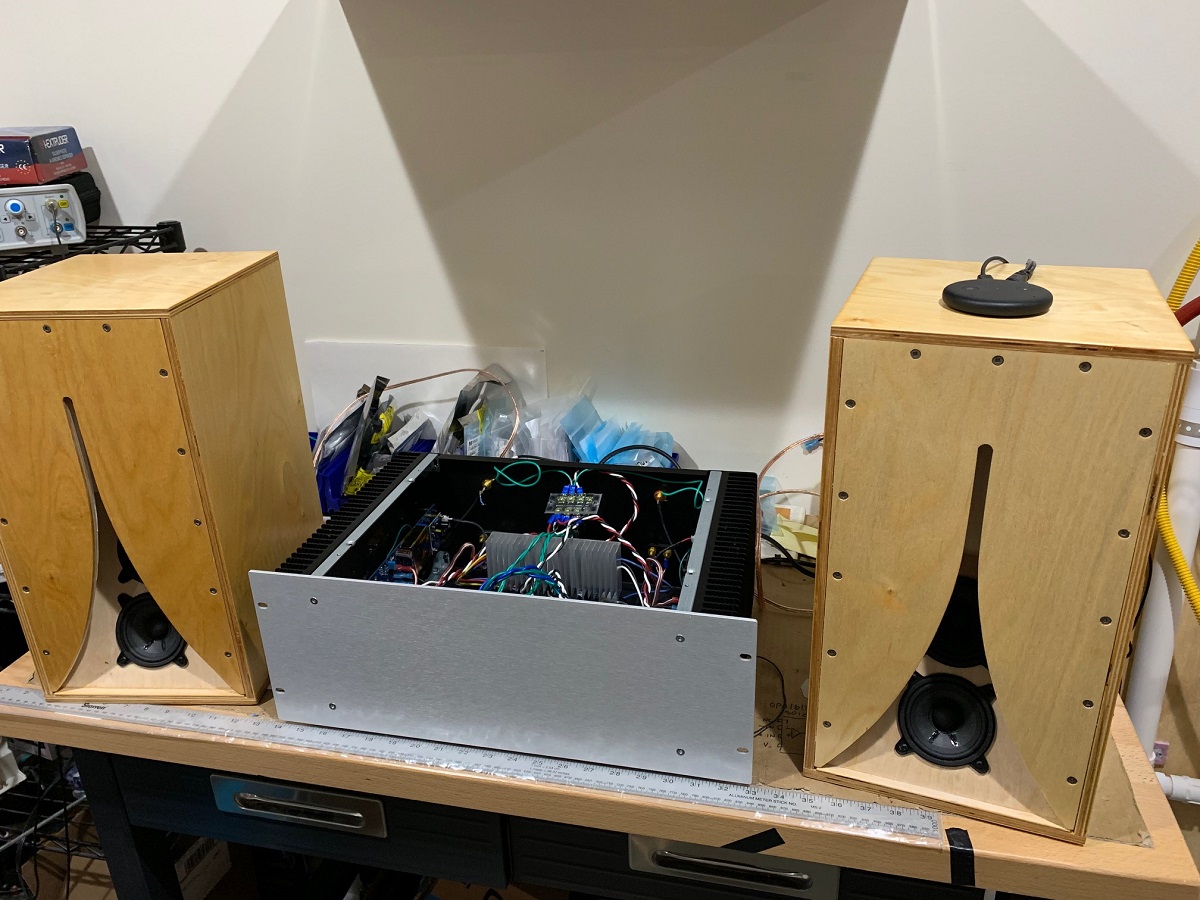
I know many of you are curious about whether or not a single SLB can be used to power a typical Nelson Pass 25w Class A amp. I have finally tested the SLB with a M2X variant and a single Antek 300VA 22v (model AS-3222) trafo with a pair of secondaries for both stereo channels. I know that using dual power trafos and two SLB's would result in a good setup, typically free of ground loop hum artifacts. Well, to achieve a ground loop and hum-free setup with only a single power trafo is challenging and I was originally getting some serious hum.
However, with some thought and debugging, I think I have revealed the path to a hum-free. The hum was bad the moment both RCA input connectors were plugged in. With one plugged in, it was fine so I knew that the source of the hum was a ground loop through the common in the RCA connectors at the source (in this case, an Amazon Echo Input). So, I cut the ground between the RCA panel jack and the M2X PCB and instead, connected each RCA ground to the SLB PSU star hub ground. On my prototype SLB, I did not have enough ground connectors on the board itself, so I used the terminal block where the SLB splits in a 'Y' to the two M2X amp modules.
This removed the ground loop hum to the point that I could only hear it with my ear about 2-3 inches away from the speaker cone (in this case, a 93-94dB sensitve 0.53x Karlsonator with dual 3F25-16's).
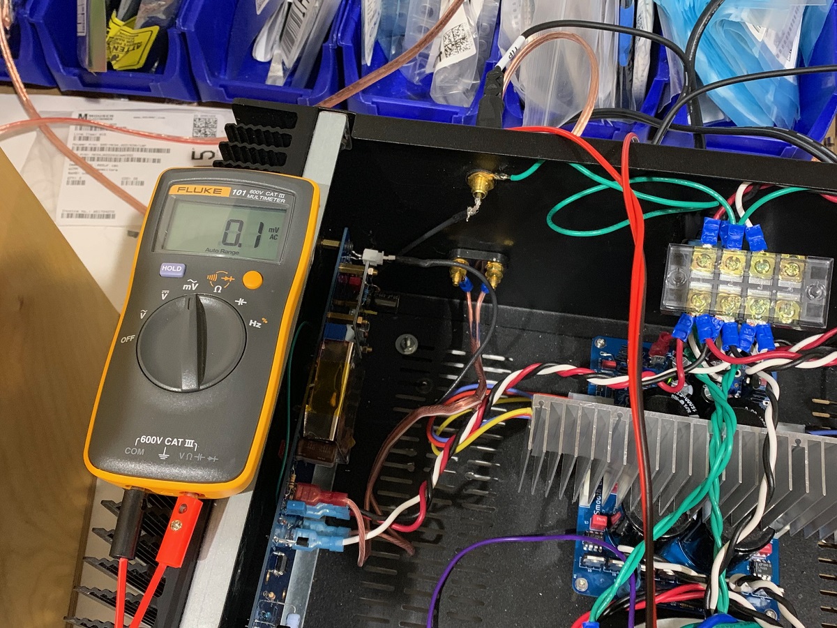
It sounds quite nice, and I don't think anyone would complain of hum at normal listening distances, and even at 3 feet away, the amp sounds silent now with input turned off. Measuring the output at the speaker with my Fluke 101 in AC mV rms, I get 100uV rms on the left and 200uV rms on the right channel. This is with mu-metal shielding on the Edcor trafos and the Antek mounted in the front away from the Edcors. The 100uV rms is actually the lowest I have ever measured with the M2 or M2X, indicating that the PSU is doing its job well.
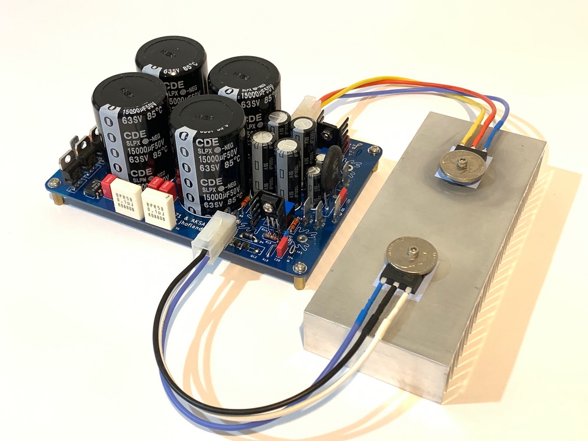
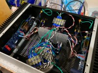
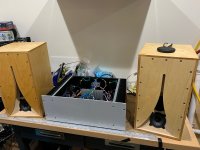
Here is the setup with the SLB in the middle-back (you can see the pass-transisor heatsink fins), note the green ground wires from the star hub to the RCA panel jacks:
Here is the output AC mV rms on the left channel on the Fluke 101 showing 0.1mV rms:
Here is the amp with the 0.53x Karlsonator speakers (dual 3FE25-16 drivers):
Some test condition notes:
Trafo is Antek AS-3222
Source is Amazon Echo Input (no built in speaker)
SLB is running 3.0v drop and output voltage rails are +/-25.4vdc
M2X is running at (self regulating) 1.38A bias current with 0.47R source resistors
Temp of pass-transistor heatsink (150mm x 50mm x 25mm $6 unit from eBay) is 53C
Temp of 4U Dissipante case heatsink is 45C
I know many of you are curious about whether or not a single SLB can be used to power a typical Nelson Pass 25w Class A amp. I have finally tested the SLB with a M2X variant and a single Antek 300VA 22v (model AS-3222) trafo with a pair of secondaries for both stereo channels. I know that using dual power trafos and two SLB's would result in a good setup, typically free of ground loop hum artifacts. Well, to achieve a ground loop and hum-free setup with only a single power trafo is challenging and I was originally getting some serious hum.
However, with some thought and debugging, I think I have revealed the path to a hum-free. The hum was bad the moment both RCA input connectors were plugged in. With one plugged in, it was fine so I knew that the source of the hum was a ground loop through the common in the RCA connectors at the source (in this case, an Amazon Echo Input). So, I cut the ground between the RCA panel jack and the M2X PCB and instead, connected each RCA ground to the SLB PSU star hub ground. On my prototype SLB, I did not have enough ground connectors on the board itself, so I used the terminal block where the SLB splits in a 'Y' to the two M2X amp modules.
This removed the ground loop hum to the point that I could only hear it with my ear about 2-3 inches away from the speaker cone (in this case, a 93-94dB sensitve 0.53x Karlsonator with dual 3F25-16's).
It sounds quite nice, and I don't think anyone would complain of hum at normal listening distances, and even at 3 feet away, the amp sounds silent now with input turned off. Measuring the output at the speaker with my Fluke 101 in AC mV rms, I get 100uV rms on the left and 200uV rms on the right channel. This is with mu-metal shielding on the Edcor trafos and the Antek mounted in the front away from the Edcors. The 100uV rms is actually the lowest I have ever measured with the M2 or M2X, indicating that the PSU is doing its job well.
Here is the setup with the SLB in the middle-back (you can see the pass-transisor heatsink fins), note the green ground wires from the star hub to the RCA panel jacks:
Here is the output AC mV rms on the left channel on the Fluke 101 showing 0.1mV rms:
Here is the amp with the 0.53x Karlsonator speakers (dual 3FE25-16 drivers):
Some test condition notes:
Trafo is Antek AS-3222
Source is Amazon Echo Input (no built in speaker)
SLB is running 3.0v drop and output voltage rails are +/-25.4vdc
M2X is running at (self regulating) 1.38A bias current with 0.47R source resistors
Temp of pass-transistor heatsink (150mm x 50mm x 25mm $6 unit from eBay) is 53C
Temp of 4U Dissipante case heatsink is 45C
Attachments

Last edited:
Thank you so much for all of your hard work. I understand that you took into account the ESR ratings of the capacitors in your design. In effort to use some of the caps I have on hand, what are the target ESR ranges for the specific caps in the circuit?
You have noted that changing R17 & R18 to 1.5(?)R from a 10R/wire link improves the ripple rejections. Those values are based on the transistors used and are not dependent on the transformer, correct?
What value should RV1/2 be at when first applying power to the circuit?
Which transformer did you use for determining the values of C1-4 & R1-2? As I understand it those component values are based on the transformer used and the best results are achieved by measuring the response for different values.
Other than the heatsink part number for the BD139/140 driver transistors are there any other changes to the BOM or application specific components to consider?
Thank you so much for all of your hard work. I understand that you took into account the ESR ratings of the capacitors in your design. In effort to use some of the caps I have on hand, what are the target ESR ranges for the specific caps in the circuit?
You have noted that changing R17 & R18 to 1.5(?)R from a 10R/wire link improves the ripple rejections. Those values are based on the transistors used and are not dependent on the transformer, correct?
What value should RV1/2 be at when first applying power to the circuit?
Which transformer did you use for determining the values of C1-4 & R1-2? As I understand it those component values are based on the transformer used and the best results are achieved by measuring the response for different values.
Other than the heatsink part number for the BD139/140 driver transistors are there any other changes to the BOM or application specific components to consider?
Lots of good questions. I’ll try my best to answer, perhaps Jhofland can chime in on the snubber question.
Just don’t pick “low ESR” caps. They are usually more expensive and have ESR in the sub 10mOhm range. Usual 60mOhm (at 120Hz) are better as they don’t cause a huge current spike during the charge cycle.
For the snubber we use a typical value but for best results you should use an OScope and a pot to adjust until the ringing is minimal then CJS ge our for equivalent resistor. I don’t notice any ringing and suspect that an ideal bridge shuts on/off at the crossover so the voltage is zero at the switch.
The Rv1 value just leave in the mid point at turn on. If you have a scope you can adjust it for max ripple reduction vs a dropout voltage you can live with. There’s really only about a 1v range here anyhow. In general, a larger dropout voltage, gives less ripple.
The resistors 10R, 2R2, 1R5 etc between the output and emitter of the master on the CFP provides damping of oscillations vs gain for reduction of ripple. It does change for different Hfe on the transistors. But a value circa 1R5 to 2R2 should work well.
The heat sinks are the usual Aavid or Fischer profiles. I just use a small stamped aluminum sink as they heat dissipation is not that much. Maybe 250mW to 500mW max.
Is it too late to get 4 boards?
-Michael
Not at all - I will send you invoice.
Let's see if I can reply to the transformer snubber question. The goal of the snubber network is to contain the oscillations in the transformer secondary that get excited each half cycle when the rectifying diodes or in our case, the rectifying FETs, turn off. If you choose to tune it exactly it's a matter of following the process Mark Johnson has documented with the transformer plus the fixture to excite that oscillation. And an oscilloscope to see what's happening. The windings not being tested should be shorted You then choose convenient values for the two capacitors and adjust the resistance until the oscillation is damped out. Mark recommends the C in the RC leg be about 15x that of the other C. My choice was somewhat different. The value of R is not a knife edge value so getting close is good enough. I chose capacitor values of 10nF and 100nF and a resistor value that's in the ballpark based on use in other circuits. If you want to get closer use Mark's fixture and test accordingly.
Is there any reason why C5/6 are film instead of ceramic? The LT4320 data sheet calls out a 1uF ceramic to be placed as close as possible to the output pins of the IC.
Would the use “audio grade” caps make difference in the performance of the power supply?
My hunch is that it doesn’t matter if it’s film/ceramic and that audio grade caps in the power supply is a waste of money, but I don’t like to guess.
Would the use “audio grade” caps make difference in the performance of the power supply?
My hunch is that it doesn’t matter if it’s film/ceramic and that audio grade caps in the power supply is a waste of money, but I don’t like to guess.
You want a low ESR cap and they do make 1uF X7R cap in through hole radial leads. I am not sure what the spec on Wima 1uF 100v MKS metallized film is vs X7R at 120Hz, but probably wouldn’t hurt to use the X7R here. I think the x7R is probably better. In general caps in the PSU section doesn’t influence sound unless they contribute to noise or hum. The 1uF cap bypassing the LT4320 is simple to provide stability. If it is stable and not oscillating, it’s probably doing its job.
- Home
- Group Buys
- The SLB (Smooth Like Butter) Active Rect/CRC/Cap Mx Class A Power Supply GB