You have a few more watts to play with then in your M2X. Which brand and size In VA transformer are you using?
Toroidy Supreme Audio with 2x20v secondaries. I’m very happy with the 26v rails under load. A bit above standard, but I don’t want to try it any higher.
Hello - I am having trouble deciding what size transformer to get for my Burning Amp 3 project. I am using two SLB PS boards for dual mono. I get two wildly different numbers based on whether I follow the quoted text below or the Burning Amp 3 Build Guide suggestions.
Per the Burning Amp 3 build guide, a good rule of thumb is to use 50VA per stereo pair of output devices per channel. Since the board has 3 pairs and I am using a +/- 32v PS, I would use a 24+24v 150VA (minimum) per channel.
However, according to XRK's suggestion below, I would need a 28+28v 500VA per channel. I am biasing my mosfets a little higher (.068ohm source resistors) so here is the math, per the quote below:
32v supply + 3v for cap Mx + 4v for sag = 39v. 39 / 1.4 = 28v
32+32 x 2.64A = 168VA. 168 * 3 = 508VA.
The 2.64A comes from the BA3 build guide as .3v / .068ohms = .44A per device * 6 devices = 2.64A per channel.
I do not know which is correct for my build - the 28v seems logical, but the hugely different VA numbers are concerning. Should I maybe just get two 300VA transformers - split the difference?
What are your thoughts?
Per the Burning Amp 3 build guide, a good rule of thumb is to use 50VA per stereo pair of output devices per channel. Since the board has 3 pairs and I am using a +/- 32v PS, I would use a 24+24v 150VA (minimum) per channel.
However, according to XRK's suggestion below, I would need a 28+28v 500VA per channel. I am biasing my mosfets a little higher (.068ohm source resistors) so here is the math, per the quote below:
32v supply + 3v for cap Mx + 4v for sag = 39v. 39 / 1.4 = 28v
32+32 x 2.64A = 168VA. 168 * 3 = 508VA.
The 2.64A comes from the BA3 build guide as .3v / .068ohms = .44A per device * 6 devices = 2.64A per channel.
How to size the trafo? Depends on the brand a bit. I would size the VA rating at 3x nominal requirement to reduce sag and saturation. So for +/-24v at 1.25A that’s 48v x 1.25A that’s about 200VA and voltage at required rails plus 3v for the cap Mx and probably 4-5v more for sag. So 24v +3v + 4v = 31v. Now divide by 1.4 and you get 22v. So for the typical 25w Class A amp, use dual 200VA 22v trafos one per channel. Note that some brands like Antek sag more than others so step up one more notch to 24v. But maybe a Talema or Toroidy is fine at 22V. Yes, dual secondaries not center tapped. One more thing, it never hurts to go up one more notch in VA rating either so dual 300VA would assure you of even better performance.
I do not know which is correct for my build - the 28v seems logical, but the hugely different VA numbers are concerning. Should I maybe just get two 300VA transformers - split the difference?
What are your thoughts?
If this is the build guide,
BA-3 Amplifier illustrated build guide
It shows 6 sets of 1ohm resistors and there is a note that says they can be replaced by 0.68ohm resistors. I am not sure 0.068ohms (or was that a typo?) you used for the calculation is correct.
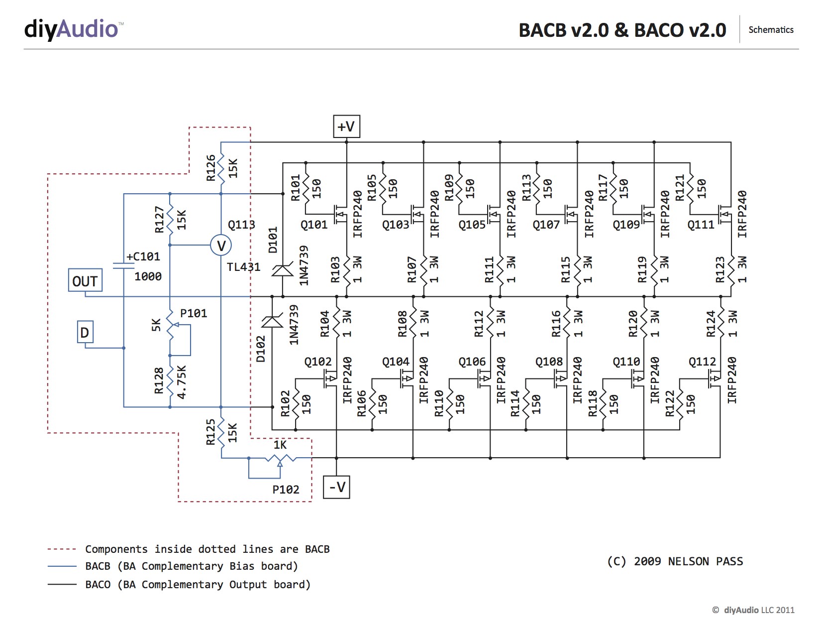
So I think current per pair is 0.3v/0.68ohm. = 0.44A (same current flows through in series for the other source resistor in same pair). Total current is 0.44A x 3 or 1.32A. Power required is 32v x 2 x 1.32A = 84w or 84VA. Typically I like to size my trafos 3x the nominal VA to reduce sag. 84VA x 3 is 253VA. So get 300VA trafo.
To get 32v rails you need to add 3v drop from SLB and 4v drop from sag. 32v + 7v is 39v. Divide by 1.41 to get ac V. That’s 28vac.
So get a 300VA 28v trafo per channel. If getting another brand than Antek, the sag may be less. Toroidy, Avel Lindbergh etc might be 25v trafo...
Antek model AS-3228 or something like that.
BA-3 Amplifier illustrated build guide
It shows 6 sets of 1ohm resistors and there is a note that says they can be replaced by 0.68ohm resistors. I am not sure 0.068ohms (or was that a typo?) you used for the calculation is correct.
So I think current per pair is 0.3v/0.68ohm. = 0.44A (same current flows through in series for the other source resistor in same pair). Total current is 0.44A x 3 or 1.32A. Power required is 32v x 2 x 1.32A = 84w or 84VA. Typically I like to size my trafos 3x the nominal VA to reduce sag. 84VA x 3 is 253VA. So get 300VA trafo.
To get 32v rails you need to add 3v drop from SLB and 4v drop from sag. 32v + 7v is 39v. Divide by 1.41 to get ac V. That’s 28vac.
So get a 300VA 28v trafo per channel. If getting another brand than Antek, the sag may be less. Toroidy, Avel Lindbergh etc might be 25v trafo...
Antek model AS-3228 or something like that.
Last edited:
Thanks for the quick reply 🙂 Yes, definitely was a typo on the .068 value. I was unaware on the current per pair - so that definitely changes the calculation. A dual 28v 300VA transformer per channel seems more reasonable for this amp. Thank you 🙂
There is a lot of talk in this thread about class a amps having a constant current draw. But that is not true for class a push-pull amps like F5, F4, BA-2 and so on. The current draw per rail is not constant at all for those amps. I guess the solution is to ad some more caps after the SLB, they would be for handling the current demand from the output stage and not ripple filtering. Does anyone have an idea on how to calculate the capacitance needed. I have been thinking about that for a while but have to realize I am not competent enough 🙂
The key to design calculations is to start with your own personal demands ("requirements"): What do I actually WANT? Quantify it; put it in numbers.
Then write the equation which calculates the number you want; it will be a function of "C", the total amount of capacitance. Solve your equation for C. Subtract the amount of capacitance you've already got, and out pops the additional capacitance you must somehow include, to get up to the required total capacitance.
_
The requirements part is the hard one. I want to have enough C so that there is never a situation where the caps are empty so the output stage draws current directly from the cap mx. So how to define that worst case? I can measure the current demand when playing music at the max volume my ears can stand. But how to find the worst case music peace? It must be something with frequent large transients I guess?
You can design for the case that gets you what nominally Mr Pass designed it for. Typically 4x 22,000uF per channel. Just use the SLB to feed that cap bank and you know you have AF least enough. Here is how I would do it.
Probably overkill as that is CRC. So try adding 22,000uF per rail between the cap Mx and the amp. Listen to music real dynamic stuff at loud SPL. See if bonks out. If it does, add more C.
Probably overkill as that is CRC. So try adding 22,000uF per rail between the cap Mx and the amp. Listen to music real dynamic stuff at loud SPL. See if bonks out. If it does, add more C.
You can design for the case that gets you what nominally Mr Pass designed it for. Typically 4x 22,000uF per channel. Just use the SLB to feed that cap bank and you know you have AF least enough. Here is how I would do it.
Probably overkill as that is CRC. So try adding 22,000uF per rail between the cap Mx and the amp. Listen to music real dynamic stuff at loud SPL. See if bonks out. If it does, add more C.
Sounds like a good approach!
You can design for the case that gets you what nominally Mr Pass designed it for. Typically 4x 22,000uF per channel. Just use the SLB to feed that cap bank and you know you have AF least enough. Here is how I would do it.
Probably overkill as that is CRC. So try adding 22,000uF per rail between the cap Mx and the amp. Listen to music real dynamic stuff at loud SPL. See if bonks out. If it does, add more C.
Does this apply to both class A and AB.or jusr class AB?
I think Class AB amps tend to have higher PSRR and may not need a cap Mx. they do need a large dynamic reserve for high peak currents though. Size the caps as if you did not have a cap Mx and that should provide the headroom you need. So if a Class AB amp has 10,000uF per rail downstream of the bridge, that’s a good value to have.
Hi x;
Why dont we just use a single resistor instead of Thermistor for break ground loops for chassis return?
Why dont we just use a single resistor instead of Thermistor for break ground loops for chassis return?
potstip, check Post #207 for an explanation.
Note that it's not post #207 in the SLB thread! It is this thread "Xmas Amp - Dibya's TDA7293 by Jhofland".
Andy
This is interesting - adding a cap bank after the SLB. A noob question - do you simply add caps in series (on both the + and - SLB output rails) to build this bank, or is there some other way to wire the caps with respect to ground?You can design for the case that gets you what nominally Mr Pass designed it for. Typically 4x 22,000uF per channel. Just use the SLB to feed that cap bank and you know you have AF least enough. Here is how I would do it.
Probably overkill as that is CRC. So try adding 22,000uF per rail between the cap Mx and the amp. Listen to music real dynamic stuff at loud SPL. See if bonks out. If it does, add more C.
- Home
- Group Buys
- The SLB (Smooth Like Butter) Active Rect/CRC/Cap Mx Class A Power Supply GB