Re: Just my 2 cents
Can I point out that this is linear (w.r.t. Eo). If that's all there is to it, then measuring the behaviour with sine waves will tell you everything you need to know about the behaviour with any signal.
If so, skin effect doesn't (IMO) provide any insight into 'mysterious' properties claimed for audio cables. It falls precisely into the same category as cable R's, L's and C's.
Cheers
IH
CheffDeGaar said:Just to sum up for dummies like me, (...)
E(z,t)=Eo.exp(-gamma*z)exp(j*omega*t)
Can I point out that this is linear (w.r.t. Eo). If that's all there is to it, then measuring the behaviour with sine waves will tell you everything you need to know about the behaviour with any signal.
If so, skin effect doesn't (IMO) provide any insight into 'mysterious' properties claimed for audio cables. It falls precisely into the same category as cable R's, L's and C's.
Cheers
IH
Linearity with sine waves doesn't guarantee that it will behave linearly with complex waveforms. (unfortunately, that certainly flies in the face of school of superposition, doesn't it?)
That is based on the fact that self inductance of the wire is actually current slew rate dependent, and not frequency dependent per se. The reaction of a wire to high slew rates would appear to be history dependent.
I do not know if that will have any audible effect in the 20 microsecond realm, but I look to test that premise. My test setup is not up and running yet..life gets in the way..
Sully
Sure..a complete and utter chaotic mess..(I'm in the middle of a move, everything I own is up against a wall in a basement..)
Last first..My 4 ohm 50 watt load is a non reactive type..Don't know it's inductance, as my meter is not useable as is to measure under 10 nanohenries. But is configured as a combination coaxial, 36 pole magnet, it's design being the complete cancellation of inductive storage.
V tap pickup is also setup to eliminate the dB/dt error associated with external loop pickup...this is a big problem with low impedance, high current measurements.
Power is a qsc rmx 1450.
Signal source is a HP3325A synthesizer.
Scope is a toy scope, tek 475. Looking to replace that with a 24/192 card for storage.
Making an IA setup for comparing signals at each end of the speaker wire.
Tried a CD burned with test signals..sampling interval is within the time shift's I'm looking for..no good.
Tried a 44K soundcard..found that it has a 2 input mux, uses one A/D..so, introduced a time shift. Hopefully, the 24 bit card is a real two channel synchronized device..
And, another load, to allow a bi-laterally symmetric run using two different "hot" runs, sharing a common ground.
Steve Eddy had posted a pic of the load earlier.
Sully
sully said:Linearity with sine waves doesn't guarantee that it will behave linearly with complex waveforms. (unfortunately, that certainly flies in the face of school of superposition, doesn't it?)
That is based on the fact that self inductance of the wire is actually current slew rate dependent, and not frequency dependent per se. The reaction of a wire to high slew rates would appear to be history dependent.
Sully
I admit to have here some difficulties. As Ian explained, you can have all the behaviours with any signals in time domain just measuring with sine waves, provided you can have all the frequencies. Just basic Fourier analysis with sine wave decomposition. 😉
Linearity is garanteed here, provided only that the material characteristics (sigma, epsilon, mu) remain E field or H field independent. They can be time (or frequency) dependent, the relation still applies. The "history" effect you mention here just reflects a frequency dependence, which is translated in a convolution product in time-domain (memory effects).
But just remember that the "inductance" you mention here is an "easy" way to understand phenomena. It is derived from Maxwell's equations. To be rigorous, we should have only to deal with E,H fields, surface current densities, charge densities, and all their subsequent variations with time. Just plug in a dispersive (frequency dependent) conductivity, time varying medium properties, etc...
The final way is to solve the Maxwell's equations in time domain, where even field-dependant material properties can be taken into account. There are solvers for such purposes, but I think it is far beyond the scope of this thread.
CDG: ""I admit to have here some difficulties""
At least I don't feel so lonely now..thought I was the only one having difficulties with this..
Yah, I like the inductance approach..
per History: think of some examples...First..a wire with ten amperes dc..internal energy stored per inch is .03u *.5 *100, or .15 e-6 joules per inch.
And a second wire with no current.
For both, add -10 amperes in in 1 nanosecond.
First wire....current is now zero. stored energy of .15e-6 ? where does that energy go? Will this wire inductively kick, returning the storage? ALA Hawksford?
second case: there is no stored energy...the skin effect has prevented the current from driving into the conductor, so, there is no energy stored within.. a conundrum...does this wire now consume some energy over time to suck up and produce internal magnetic field? (course it does).
But in the first, energy has to return to the system somehow..the second, energy must be consumed..but the storage mechanism is the self inductance, which has a slew rate dependence..
Can self inductance be modelled using time invariant elements? That is, can many inductive and capacitive elements be used to simulate the real workings of a wire under skin effect? The use of wave propagation normal to the surface does not carry with it any intuition regarding the actual skinning..
Sully
Well folks, let's clear up a few things.
First, Sully is Jneutron on 'Audioasylum.com'.
We have discussed this to death on 'Propellerheads' up until yesterday.
Hawksford sent many of us a complete 80+ page copy of his original work. This is what we should discuss from, in order to fully understand Hawksford, and many of us have done so. My email address is: jcurl@earthlink.net
I will email a copy of Hawksford's article to everyone who sends me an email for it. I am a colleague of Dr. Hawksford, and I'm sure that this is OK.
I'm sure that Dr Hawksford would welcome any constructive feedback on his work.
Hey hey, John...how's it goin??
Doesn't John Atkinson own the rights to the essex articles??
Without his express written consent, I have not presented that particular offer to forums, as there are ownership and copyright issues..perhaps you should re-think that offer..unless JA has actually given consent..
John Curl ""First, Sully is Jneutron on 'Audioasylum.com'. ""
Took you a while...guess the equations and tech talk gave me away...oh well.
Oh, actually...I am jneutron over there, not Jneutron. Seems that after changing my moniker there to the same as the one I had at AR, I found that there was a "J" (caps) neutron...alas, one change was confusing enough..Sully (from monsters Inc) was my second choice...so I used that here.
That was a honker of a document, wasn't it? 87 pages..It is unfortunate that the actual test stuff was virtually identical to the 95 article.
BTW, where did you get that Iron skin depth from...Hawksford, or did you look up the element..
Cause a high mu wire is gonna skew the test results all to heck..might as well add a one millihenry inductor to the series resistance of a shorted two meter length of wire...
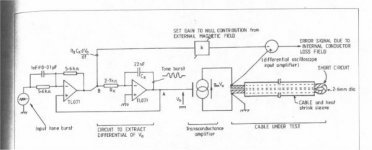
Take a look at the test setup..note how he says the feed forward nulling signal is for external inductance..without regard to the whopping self inductance of a steel wire.
Also..look at what he is looking across..the "error signal due to loss field" part..he is summing the externally derived inductance component with the signal across the wire..but..the wire represents a low impedance...the resistance of the wire, which is rather low, and the self inductance of the steel, which is, what.. .03 microhenries per inch with mu=1...40 inches (say a meter), mu of , guessing, 1000...that would be, 30 microhenries per inch, 1200 microhenries for one meter steel zip.. 1.2 millihenries..
Now, the wire..copper #12 is 1.71 milliohms per inch, steel, guess five times that?...times 80 inches..684 milliohms..
Now, 684 milliohms in series with 1.2 millihenries...how hard is it to see the phase shift he measured, and how it is because of the self inductance of the steel wire???? scope photo next post..
Man, I love being able to include jpegs...major cool.
BTW...anyone worth their weight in salt (and experience with coaxial hf shunts)would see the error components here when trying to view low impedance at anything other than DC.
Cheers, John
Doesn't John Atkinson own the rights to the essex articles??
Without his express written consent, I have not presented that particular offer to forums, as there are ownership and copyright issues..perhaps you should re-think that offer..unless JA has actually given consent..
John Curl ""First, Sully is Jneutron on 'Audioasylum.com'. ""
Took you a while...guess the equations and tech talk gave me away...oh well.
Oh, actually...I am jneutron over there, not Jneutron. Seems that after changing my moniker there to the same as the one I had at AR, I found that there was a "J" (caps) neutron...alas, one change was confusing enough..Sully (from monsters Inc) was my second choice...so I used that here.
That was a honker of a document, wasn't it? 87 pages..It is unfortunate that the actual test stuff was virtually identical to the 95 article.
BTW, where did you get that Iron skin depth from...Hawksford, or did you look up the element..
Cause a high mu wire is gonna skew the test results all to heck..might as well add a one millihenry inductor to the series resistance of a shorted two meter length of wire...
Take a look at the test setup..note how he says the feed forward nulling signal is for external inductance..without regard to the whopping self inductance of a steel wire.
Also..look at what he is looking across..the "error signal due to loss field" part..he is summing the externally derived inductance component with the signal across the wire..but..the wire represents a low impedance...the resistance of the wire, which is rather low, and the self inductance of the steel, which is, what.. .03 microhenries per inch with mu=1...40 inches (say a meter), mu of , guessing, 1000...that would be, 30 microhenries per inch, 1200 microhenries for one meter steel zip.. 1.2 millihenries..
Now, the wire..copper #12 is 1.71 milliohms per inch, steel, guess five times that?...times 80 inches..684 milliohms..
Now, 684 milliohms in series with 1.2 millihenries...how hard is it to see the phase shift he measured, and how it is because of the self inductance of the steel wire???? scope photo next post..
Man, I love being able to include jpegs...major cool.
BTW...anyone worth their weight in salt (and experience with coaxial hf shunts)would see the error components here when trying to view low impedance at anything other than DC.
Cheers, John
Attachments
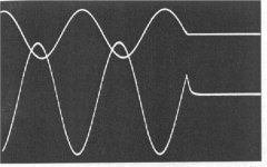
Here's the scope photo.
Notice the phase shift of the sine wave... then the reaction to the abrubt cut of the sine at zero.
This is a classic example of an inductive current shunt error when the shunt collapsing field produces an error voltage in the voltage reading..It is not a real entity, but the sum of current and error voltage..
For real current shunts, this error is eliminated by running the v tap wires down the geometric center of the shunt.
For Hawksford's setup, that was not possible...or tested for.
Cheers, John
Attachments
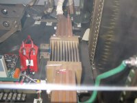
And here is an example of a current shunt..
This is a DC one, 250 micro-ohms, that is used for current viewing of a half sine, 6000 amp pulse.
When the half sine is fed into this, this produces a voltage which is proportional to the current..Unfortunately, it also adds an error signal which is proportional to the rate of collapse of this shunt's magnetic field..For low impedances, like this shunt, (and shorted wire lengths), that collapsing field generated voltage is a large proportion of the voltage drop across the element. At higher frequencies, the voltage is higher; it is proportional to the rate of change, therefore frequency.
This shunt produced the exact same waveform Hawksford shows..
If you look closely, you will see a teflon tube covered wire that drops into the shunt in the geometric current center (well, ok, there's an odd number of plates) 🙄 That wire is put in the middle of the resistor to approximate a coaxial shunt as much as possible..By doing this, the error across the shunt was reduced to below ten millivolts, from a signal of about 1.4 volts peak.
Sorry for the hazy look of the picture..It's on the other side of a 1/4 inch thick lexan blast shield. (case I blows it up)
Cheers, John
Attachments
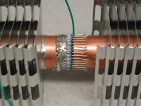
And here is my newest load resistor in the middle of the build.
It is made of 36 resistors in parallel, and coaxial, using 3/4 slant fin. Notice that in between each resistor is a wire. Those are used to return the current back in between the resistors. That makes a 36 pole magnet structure. The proximity of the return wires helps reduce the stored energy and inductance. This 36 pole magnet has internal fields that drop as 2^-35 power radially, and 2^-37th power externally..Just before those wires hit the 3/4 tubing, they bend inward and are soldered to a coaxial piece of 1/2 inch tube. So the current signal is fed coaxially from the right, and the v tap signal is picked up by that green wire and another connected to the 3/4 tube right there. In that way, db/dt pickup from the v tap wires is reduced to mud.
In the furture, I think I will go with a larger diameter tube, and use resistors for the return path instead of wires, as I can't guarantee current sharing between the wires that well, and it is the balalced currents that makes this load have inductance below 10 nano-henries right now..
Cheers, John
Attachments
john curl said:
We have discussed this to death on 'Propellerheads' up until yesterday.
Actually, I have tried to get a discussion going there..alas, far too many have simply bashed me for my efforts...without discussing anything technical at all..some actually call my questions nitpicking, or call it "BS"...go figure..
Tis a shame, actually..as there are a few there that are really nice, and seem to comprehend my "rantings"..
Here, there seems to be people who understand crawling out of the woodwork..major refreshing, that is...
And at first glance, the moderating here with that texas thing is really nice..good for keeping the people who prefer to criticize at bay..
I look forward to some tech talk John C....
Cheers, John
Sully, I've really enjoyed your contributions. A question: when you say that the tail of the tone burst is not a "real entity," what do you mean? When I see a trace on a 'scope, it sure seems real to me, unless it's a measurement-induced error. The tail looks like what I'd expect from driving a small inductance.
Sy, and others, please look at the exchange in 'propellerheads' on audioasylum.com on this topic. Same inputs, just that my associates and I have been left out. I have personally contacted Dr. Hawksford on this subject, and others have asked for more input from Dr. Hawksford on his test procedure. Many questions are answered in his original work published in 'HFN' in about 1985, and especially in his 80+ page original submission that he has personally sent to me as well as others concerned with this topic. This thread, so far, has only omitted his recent input on his 'skin effect' test, that he originally emulated by both computer simulation and by measurement. For the record, 'steel' wire was used to INCREASE the skin effect by a factor of approximately 4 at 1KHz. It is is the literature that this will occur with 'iron' (with a mu of 100 or so). instead of copper wire. Dr. Hawksford is interested in maximizing the skin effect at 1KHz or so, in order to see it easily with an oscilloscope readout. This is why he used 'iron' instead of copper in this one test.
sully said:
per History: think of some examples...First..a wire with ten amperes dc..internal energy stored per inch is .03u *.5 *100, or .15 e-6 joules per inch.
And a second wire with no current.
Well, is it a real setup ? I mean, to provide 10amps dc, need to have a generator, connected at both sides of a wire. Or should we imagine infinite wires floating in space with no connections ?
Nevertheless, it's just a case of initial conditions: the 1st wire is charged. Side note : if memory serves, the current is defined as the variation of charges w.r.t. time (I=dQ/dt, Amps=Coulombs/sec). Thus there must be a generator if 10 Amps are measured...
On the other side, if we assume no connection, the wire only has potential energy, and therefore an electrostatic potential. But no current can be defined here : just charge densities, fields, etc...
For both, add -10 amperes in in 1 nanosecond.
First wire....current is now zero. stored energy of .15e-6 ? where does that energy go? Will this wire inductively kick, returning the storage? ALA Hawksford?
second case: there is no stored energy...the skin effect has prevented the current from driving into the conductor, so, there is no energy stored within.. a conundrum...does this wire now consume some energy over time to suck up and produce internal magnetic field? (course it does).
But in the first, energy has to return to the system somehow..the second, energy must be consumed..but the storage mechanism is the self inductance, which has a slew rate dependence..
Let's forget inductances here, and look at the problem from the EM side. Electrostatic laws do no apply here anymore, since it's purely transient. Applying a pertubation on wires (adding a current, a field, or whatever you want) destroys the equilibrium. It begans to move the charges in the wires, creating currents and EM fields. Fields created by the currents on each wire will interact with the other wire, by EM coupling. The current on each wire will be modified by the external field, and the resulting modification will change the fields generated by the wire, and this fields will influence the current on the other wire and so on....
And where does the energy go ? First, wires have a conductivity (sigma), otherwise this thread will be objectless 😉 and some energy is dissipated by Joule effect (sigma*E*E). The other part is radiated. The wire has to lose some energy to allow fields to be radiated.
Now concerning the perturbation itself : -10 Amps in 1 ns. Transients do have a wide bandwidth, depending on the shape of the pulse (gaussian, biexponential, square, etc...) More interesting, the frequency band of the pulse ranges down to low frequencies. Thus some part of the "energy" contained in the pulse will penetrate deeply in the conductor, and the skin effect will not prevent this at these frequencies.
The inductance, self or mutual, you mention, is not slew rate dependent. It's a characteristic of the structure and actually depends on the geometry of the wire and on its EM characteristics. It can be seen as a transfert function, and does not depend on the signals you use. The self inductance is a way to express the ability of the structure to store energy and to release it with a delay, or some phase lag. It also takes part to express the possible resonances of a limited structure. And the mutual inductance between the wires can beseen as an easier model for an EM coupling coefficient.
Can self inductance be modelled using time invariant elements? That is, can many inductive and capacitive elements be used to simulate the real workings of a wire under skin effect?
Yep, but what approximations are made, and what do we neglect, what would be the frequency range of this model ?
Never said EM theory was intuitive 😉
The use of wave propagation normal to the surface does not carry with it any intuition regarding the actual skinning..
Sully
As Phred said earlier in this thread, "I wish I knew how to reduce Emag to simple algebra. It would have made school so much easier."
sully said:Here's the scope photo.
Notice the phase shift of the sine wave... then the reaction to the abrubt cut of the sine at zero.
This is a classic example of an inductive current shunt error when the shunt collapsing field produces an error voltage in the voltage reading..It is not a real entity, but the sum of current and error voltage..
For real current shunts, this error is eliminated by running the v tap wires down the geometric center of the shunt.
For Hawksford's setup, that was not possible...or tested for.
Cheers, John
John,
I confess not having read the entire thread, but I have a question on your waveform in this post. When you talk about the error, I assume you mean the little tail where the waveform doesn't return to zero in zero time, correct? The fact that the cutoff-point is not at zero is caused by the phase shift, right?
If that is so, isn't the error (tail) simply caused by the inductance of the current carrying conductor?
Jan Didden
Re: sigma goes to 0
Coincidentally, there is a full article in Electronics World nov 03 on skin effect. The simplyfied equation we used is shown, but also the full monty with the complex bessel function, + simplifications and error budgets. A must-read if you post in this thread.
Jan Didden
1/137 said:so as sigma goes to zero delta goes to 0?
over what range does this work?
rt
Coincidentally, there is a full article in Electronics World nov 03 on skin effect. The simplyfied equation we used is shown, but also the full monty with the complex bessel function, + simplifications and error budgets. A must-read if you post in this thread.
Jan Didden
sully said:Linearity with sine waves doesn't guarantee that it will behave linearly with complex waveforms.
Er, yes it does, that's what I mean by linearity.
If nothing in the equations depends on the absolute magnitude of the E or H values, and the system is time-invariant, meaning that it doesn't behave differently depending on what time of day the signals arrive, then any input signal can be analysed by taking its Fourier transform, solving the equations separately for each frequency, combining the results and taking the inverse Fourier transform. That's a simple matter of mathematics - there's a simple thought experiment which I'll describe if you're not convinced.
If you've been paying really close attention, there has been some mild cheating going on. At some point we say B = mu. H for the magnetic field, and assume that mu is constant - independent of the absolute magnitude of H. This is in fact untrue (particularly for, say, iron) and does indeed make the equations nonlinear.
However, I contend that this nonlinearity is present in the system anyway, and it potentially causes distortion even in the total absence of skin effect. The worst that can be said of skin effect is that it might increase the field strengths at a particular point to an extent that previously negligible nonlinearities in the system are now significant.
Cheers
IH
SY said:: when you say that the tail of the tone burst is not a "real entity," what do you mean? When I see a trace on a 'scope, it sure seems real to me, unless it's a measurement-induced error. The tail looks like what I'd expect from driving a small inductance.
You are correct..it is a real entity, in that it is seen on the scope. But two error mechanisms provide the same thing..first, a high inductance, which from JC's info below, was by using steel with a mu of 100, giving an inductance add on of .12 millihenries per meter of steel wire pair. The second is the current shunt field collapse, which is entirely fictitious w/r to the actual current in the wire.. This component of error can be seen by making a wire loop to short the scope probe, and run the loop one part against the load, the other coming away from the load at the commect point. This loop will show the field collapse error component only, as it couples magnetically to the shunt field.
john curl said:Sy, and others, please look at the exchange in 'propellerheads' on audioasylum.com on this topic. Same inputs, just that my associates and I have been left out. I have personally contacted Dr. Hawksford on this subject, and others have asked for more input from Dr. Hawksford on his test procedure. Many questions are answered in his original work published in 'HFN' in about 1985, and especially in his 80+ page original submission that he has personally sent to me as well as others concerned with this topic. This thread, so far, has only omitted his recent input on his 'skin effect' test, that he originally emulated by both computer simulation and by measurement. For the record, 'steel' wire was used to INCREASE the skin effect by a factor of approximately 4 at 1KHz. It is is the literature that this will occur with 'iron' (with a mu of 100 or so). instead of copper wire. Dr. Hawksford is interested in maximizing the skin effect at 1KHz or so, in order to see it easily with an oscilloscope readout. This is why he used 'iron' instead of copper in this one test.
While selecting steel (or iron) may increase the skin effect, it is entirely swamped by the wire inductance, which from your information, is .12 millihenries per meter of his test length. And yet, no accounting was made of that incredibly large inductance increase.. Looks like he got bit by that oversight, doesn't it? By trying to increase the skin effect by a factor of four, he increased the unaccounted for inductance of steel by a factor of 100..
This thread is dealing ONLY with his later work, not the 86 page "unification" document you keep referring to. If you look on his 86 page tome, you will see that the 95 essex article is actually a cut and paste out of the page 75 or 76 (no page numbers there) So, in the time between 86 and 95, he does not show any more work, just a re-hash of the old. At least the 86 pager doesn't have the incorrect e-field drawing typo.
What I found interesting was one statement in the tome where he said it was "satisfying" when they brought a speaker magnet close to the steel wires to test the hypothesis that the field of the magnet could alter the current profile, and saw a difference in the error function.. Unfortunately, that was an ill conceived test, as no accounting of the proximity of the high mu magnet was included, where coupling of the wire field to the high permeability material would produce a higher inductance of the wire system..
To rigorously test that premise would have required using a high field zero mu magnetic source, like a coil of copper wire with current in it to affirm that the magnetic field was responsible, and then , a zero field piece of steel to affirm that mu based coupling did not do it. Overall, a rather interesting indicator of sloppy experimental work and jumping to desired conclusions..Alas, I can only peruse the printed stuff sent me, so it is not possible to rigorously define the methods as sloppy, nor the desire to see what you want to see, so I give him the benefit of the doubt w/r to motives. Can't hang anyone for typos, you know...
In glancing through it, I also not a lot of reference to your cap dielectric testing..I look forward to reading on that, as I am interested in that subject.
CheffDeGaar said:
Well, is it a real setup ? I mean, to provide 10amps dc, need to have a generator, connected at both sides of a wire. Or should we imagine infinite wires floating in space with no connections ?
Nevertheless, it's just a case of initial conditions: the 1st wire is charged. Side note : if memory serves, the current is defined as the variation of charges w.r.t. time (I=dQ/dt, Amps=Coulombs/sec). Thus there must be a generator if 10 Amps are measured...
On the other side, if we assume no connection, the wire only has potential energy, and therefore an electrostatic potential. But no current can be defined here : just charge densities, fields, etc...
Let's forget inductances here, and look at the problem from the EM side. Electrostatic laws do no apply here anymore, since it's purely transient. Applying a pertubation on wires (adding a current, a field, or whatever you want) destroys the equilibrium. It begans to move the charges in the wires, creating currents and EM fields. Fields created by the currents on each wire will interact with the other wire, by EM coupling. The current on each wire will be modified by the external field, and the resulting modification will change the fields generated by the wire, and this fields will influence the current on the other wire and so on....
And where does the energy go ? First, wires have a conductivity (sigma), otherwise this thread will be objectless 😉 and some energy is dissipated by Joule effect (sigma*E*E). The other part is radiated. The wire has to lose some energy to allow fields to be radiated.
Now concerning the perturbation itself : -10 Amps in 1 ns. Transients do have a wide bandwidth, depending on the shape of the pulse (gaussian, biexponential, square, etc...) More interesting, the frequency band of the pulse ranges down to low frequencies. Thus some part of the "energy" contained in the pulse will penetrate deeply in the conductor, and the skin effect will not prevent this at these frequencies.
The inductance, self or mutual, you mention, is not slew rate dependent. It's a characteristic of the structure and actually depends on the geometry of the wire and on its EM characteristics. It can be seen as a transfert function, and does not depend on the signals you use. The self inductance is a way to express the ability of the structure to store energy and to release it with a delay, or some phase lag. It also takes part to express the possible resonances of a limited structure. And the mutual inductance between the wires can beseen as an easier model for an EM coupling coefficient.
Yep, but what approximations are made, and what do we neglect, what would be the frequency range of this model ?
Never said EM theory was intuitive 😉
As Phred said earlier in this thread, "I wish I knew how to reduce Emag to simple algebra. It would have made school so much easier."
Nice..wanted to cull for brevity, but I didn't find anything I could..
The verbal example with 10 amps was used solely to provide inclusion of a current in the wire prior to the step. And I used DC only to completely eliminate current profile re-distribution. In actuality, 100 hz woulda worked as well, but could confuse the point.
The inductance of a wire is dependent on the rate of change of the current within it..the internal, linearly increasing from center magnetic field causes toroidal eddy currents within..it is these current toroids which are causing the current profile to change..they add or subtract from the transport current, providing the effective profile we see.
I've tried three different ways to model the current profile so far, and nothing using standard linear components works (that I've imagined yet). I'm now trying to toy with conductor shells, with some kind of transmission line type of coupling, to introduce time dependence.
OH..a side note..So far, the equation for parallel wire inductance has the external dipole field, a length correction, and the self inductance term, which is the skin part..But, where is the proximity effect where the closeness of the opposite conductor has it's magnetic field altering the one of interest?? In other words, it looks like the skin term has been taken directly from the analysis of a single conductor, without regard to the return one..Anybody seen a modification of that term??
I must apologize for the lack of descriptive diagrams..the rather high technical content of the responses here so fast has left me red-faced, I was unprepared to provide some pics or drawings..
I must admit, it is a rather refreshing change from prophead and cable. Entire threads come and go with no technical content passing hands..a shame, actually..
Cheers, John
janneman said:
John,
When you talk about the error, I assume you mean the little tail where the waveform doesn't return to zero in zero time, correct? The fact that the cutoff-point is not at zero is caused by the phase shift, right?
If that is so, isn't the error (tail) simply caused by the inductance of the current carrying conductor?
Jan Didden
FYI, it's Hawksford's photo. And yes, he say's that little tail is the "loss component", but I contend it's inductance, especially since the wire was so magnetic. I also contend that the phase shift in the photo is a result of the .12 millihenries of the wire in series with the .684 ohms (a guessed number)of the wire..in fact, a R-L circuit.
IanHarvey said:
Er, yes it does, that's what I mean by linearity.
If you've been paying really close attention, there has been some mild cheating going on. At some point we say B = mu. H for the magnetic field, and assume that mu is constant - independent of the absolute magnitude of H. This is in fact untrue (particularly for, say, iron) and does indeed make the equations nonlinear.
Cheers
IH
I am in total agreement with your definition on linearity. And, I also have issues with considering wire inductance as a non linear element..(yes, I also deal with mu's that are non-linear, good magnet iron typically saturates in the 2 to 4 tesla range, and above that, we have to play games.)
I think I should qualify my non linear statement...as I'm not sure how to model the behaviour. I mean that the inductance of a wire is a function of the current slew, not current absolute like a mu non linearity would do...but the current derivative..and I don't yet know how that models.
Cheers, John
- Home
- General Interest
- Everything Else
- The Skin Game