sully said:Here's the scope photo.
Notice the phase shift of the sine wave... then the reaction to the abrubt cut of the sine at zero.
Supposing we had an RC low-pass filter, running at somewhere near the turnover frequency. The voltage at the output is slightly lagged w.r.t. the input when fed a continuous sinewave, as you'd expect.
When the tone burst stops, you have a capacitor with a small voltage across it being clamped to 0V via the input resistor. The output voltage will decay exponentially to zero, just as we see here.
I find thinking about R's and C's intuitively easier than L's and R's, but it's easy to transform between the two. In other words, the scope trace seems to do just what you'd expect it to.
Cheers
IH
CheffDeGaar said:
The inductance, self or mutual, you mention, is not slew rate dependent. It's a characteristic of the structure and actually depends on the geometry of the wire and on its EM characteristics. It can be seen as a transfert function, and does not depend on the signals you use. The self inductance is a way to express the ability of the structure to store energy and to release it with a delay, or some phase lag. It also takes part to express the possible resonances of a limited structure. And the mutual inductance between the wires can beseen as an easier model for an EM coupling coefficient.
For the example of zero current at t<0, think of this with a #2 awg welding wire....
At t=0, start slewing the current at 1 amp per microsecond..while this is going on, the self inductance is zero. And as long as that slew rate continues, the self inductance wil remain zero..Yes, the external field will be building, and certainly broadcasting, but the self inductance will remain at zero..
Now, instead of that slew rate, go at 1 amp per second..the inductance of the wire will be .015 microhenries per inch wire, .03 per pair.
So, the inductance of the wire is entirely dependent on the slew rate of the current. I don't know if the inductance can simply be considered as a time dependent element, or if simpler, known entities can be used in some magical combination, one that I hope can reflect physical reality.
The examples are extreme to demonstrate my thinking. I've yet to take this model down in flames, but still find the modelling packages lack the requisite complexity to attack this.
Cheers, John
This thread is completely one sided, without even contacting the author of the article, or carefully reading the text. The inductance of ANY wire used in the test is deliberately cancelled out by differential subtraction at the scope by first emulating a di/dt waveform and adjusting its amplitude in order to null of the normal inductance. It is the RESIDUE that Hawksford is attempting to bring out. The residue is generated by 'skin effect', not normal inductance.
For the record, a computer 'Matlab' emulation of the effect is also given in Dr. Hawksford's paper. If anyone wants, they can duplicate the test on a computer. If they can find something wrong with the computer simulation, then, perhaps, there might be something wrong with the physical measurement, BUT at this time they show essentially the same thing. If Hawksford's physical measurement is incorrect, then there will be a discrepency between theory and measurement. How about it folks? Anyone up to doing the computer simulation?
For the record, a computer 'Matlab' emulation of the effect is also given in Dr. Hawksford's paper. If anyone wants, they can duplicate the test on a computer. If they can find something wrong with the computer simulation, then, perhaps, there might be something wrong with the physical measurement, BUT at this time they show essentially the same thing. If Hawksford's physical measurement is incorrect, then there will be a discrepency between theory and measurement. How about it folks? Anyone up to doing the computer simulation?
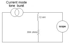
Here's a qiuck pic of the wire with it's self inductance, as per JC's mu of 100, and using a one meter (approx) length of steel wire, with an assumed resistance of .684 ohms per 2 meter length..
Being current fed, there will be a phase shift..and, when current is dropped to zero, there will be an inductive "reaction".
This model assumes the external geometric inductance has been correctly nulled out, so it was not included.
From the schematic of Hawksford's, it is unclear how the scope would couple to the collapsing mag field, so I didn't even include that error component.
Cheers, John
Attachments
john curl said:This thread is completely one sided, without even contacting the author of the article, or carefully reading the text. The inductance of ANY wire used in the test is deliberately cancelled out by differential subtraction at the scope by first emulating a di/dt waveform and adjusting its amplitude in order to null of the normal inductance. It is the RESIDUE that Hawksford is attempting to bring out. The residue is generated by 'skin effect', not normal inductance.
For the record, a computer 'Matlab' emulation of the effect is also given in Dr. Hawksford's paper. If anyone wants, they can duplicate the test on a computer. If they can find something wrong with the computer simulation, then, perhaps, there might be something wrong with the physical measurement, BUT at this time they show essentially the same thing. If Hawksford's physical measurement is incorrect, then there will be a discrepency between theory and measurement. How about it folks? Anyone up to doing the computer simulation?
Why is it one sided here, John?? we are discussing it..Well, some of us, anyway..you are welcome to provide technical input as well..should you feel up to it..
The inductance of any wire is in three parts..external geometric, a geometric modulation based on the length to spacing ratio, and the self inductance.. Hawksford clearly states, and I quote, "to null contribution from external magnetic field"...which by definition, does not include the self inductance which was increased by two orders of magnitude by the use of high mu steel as the conductor.
We agree, all the wire inductance should have been deliberately nulled out...but from his own words, the added self inductance was not considered..oops..
I have enough confidence in Hawksford's ability to run a computer simulation, even if it was 1986 era software.
We are discussing the effect here, as well as the test setup flaws..And, that is certainly not one sided..so why do you say such??
And, btw..I did contact Hawksford..but you knew that..
A very nice, eloquent man, he is..And I'm sure, that given what is being discussed here, he would be more than willing to discuss or address anything we can come up with..
As to simulation showing the same as the test setup?? Nobody else has duplicated his results..My goodness, look at that honkin phase shift, at one Khz...how come nobody's seen that in the intervening 15 years? I certainly have questions regarding the methods.. I can certainly concentrate on the test methods aspect..perhaps you can apply your knowledge of e/m theory to the simulation, checking Hawksford's grasp of theory and math???
If I were doing that analysis, I would always worry about test setup errors producing thinks I want to see (matching the simulation)..I think he didn't try to verify the accuracy of the setup...In the exact same way he put a magnet next to the wire, confirming his hypo, which I showed was not scientifically rigorous at all..
Oh, and, yes...I've read his article back and forth about a dozen times, with highlighter over all the "interesting" (shall we say) incongruities..but..one incongruity at a time..
Cheers, John
John C, I can assure you that MH will be welcome here, if he cares to participate in a technical discussion. Since he is your colleague, why not invite him to respond?
Sy, please let me send you (and others) what Dr. Hawksford has already provided us. Then, we can ask the subtle questions from him directly. 'Sully' has already contacted Dr. Hawksford with his 'correction'. It still doesn't make any sense, if the computer model already predicts this 'behavior' of the signal, to think that the results are inaccurate.
I'd greatly appreciate that, John. I think that if what Sully says has merit, the questions might be more than just subtle, but I'd rather judge after reading the extended paper; all I have on hand is the HFNRR "Essex Echo" article.
I think you can feel safe that private dissemination of a technical paper for the purpose of comment and discussion would fall under the Fair Use doctrine.
I think you can feel safe that private dissemination of a technical paper for the purpose of comment and discussion would fall under the Fair Use doctrine.
SY said:I think that if what Sully says has merit, the questions might be more than just subtle, but I'd rather judge after reading the extended paper; all I have on hand is the HFNRR "Essex Echo" article.
I think you can feel safe that private dissemination of a technical paper for the purpose of comment and discussion would fall under the Fair Use doctrine.
If what I am saying has merit, it has a huge impact on the entire article, it's premise, and the results..not subtle, as you point out.
But, isn't that why it's being discussed? To figure out the foibles, with Hawksford, me, everybody? We all make mistakes..nobody's exempt.
Unfortunately, the big paper does not provide further insight, it is the source from which the 95 article was derived (actually, mostly cut and paste).
And, note that I am referring only to the test setup for skin and it's implications..NOT any other part of the larger '86 paper.
I hope the fair use doctrine is applicable, even though I doubt the 95 essex article falls under it, JA owns that....As I understand, Hawksford sent the large tome for just that use, but I do not know who owns the rights to it.
Cheers, John
john curl said:Sy, please let me send you (and others) what Dr. Hawksford has already provided us. Then, we can ask the subtle questions from him directly. 'Sully' has already contacted Dr. Hawksford with his 'correction'. It still doesn't make any sense, if the computer model already predicts this 'behavior' of the signal, to think that the results are inaccurate.
If it's a testing error, it isn't subtle..
I did not discuss a "correction" with Hawksford..I discussed error mechanisms of the type I show on this thread. Quite detailed, in fact..Review the e-mails; you were cc'd on them.
And, if the self inductance is not accounted for, (remember, Hawksford neglected it, referring only to external field), then the question becomes "why does correct testing not match the computer model"..In that case, time to go back to the simulation blackboard..
If the desire was to increase the skin effect by a factor of four, why did he not just drop in #2 or #4 copper welding wire, instead of confounding the setup with a magnetic material?? That would have been a nice confirmation, if in fact what he derived was correct..
Thankfully, he chose to write up his entire kaboodle and publish, so that we could be having this discussion..
Cheers, John
This is where the problem lies. Hawksford is referring to the actual inductance as the 'external magnetic field' BECAUSE it resides in the external magnetic field. This is not the usual American way of describing it, however it is still accurate. He is NOT talking about interference from an external AC or DC field. He CANCELS the primary inductance in direct manner.
sully said:
For the example of zero current at t<0, think of this with a #2 awg welding wire....
At t=0, start slewing the current at 1 amp per microsecond..while this is going on, the self inductance is zero. And as long as that slew rate continues, the self inductance wil remain zero..Yes, the external field will be building, and certainly broadcasting, but the self inductance will remain at zero..
Now, instead of that slew rate, go at 1 amp per second..the inductance of the wire will be .015 microhenries per inch wire, .03 per pair.
I surely miss something outa here 🙁 . Will dive back in my old books to find what is really an inductance (not joking) ...Could you please explain to dummy-me (no dishonest modesty here) how I can calculate these figures ? Are these ones experimental values ?
The examples are extreme to demonstrate my thinking. I've yet to take this model down in flames, but still find the modelling packages lack the requisite complexity to attack this.
Cheers, John
Well, will try to find a rigorous software package to solve Maxwell's equations. Trying FDTD method looks the best, it can account for inhomogeneous, heterogeneous and tensorial materials, and non linear (field dependent) ones as well...
And John (Curl), I'd surely appreciate a copy of Hawksford's paper.
Cheers
I cannot send you the paper without your email address. You MUST send it to me. I will make a list of those interested and send the whole thing out at one time, as it takes about 1/2 hour for me to send it to anyone.
john curl said:This is where the problem lies. Hawksford is referring to the actual inductance as the 'external magnetic field' BECAUSE it resides in the external magnetic field. This is not the usual American way of describing it, however it is still accurate. He is NOT talking about interference from an external AC or DC field. He CANCELS the primary inductance in direct manner.
No, that is not where the problem lies..The actual inductance of any wire is the sum of it's external field storage, and it's internal field storage..using a mu of 100 wire makes it's internal storage 15 times higher than the external storage (typical #18 awg zip as an example.).
That's why I have been careful to differentiate (no pun intended) the inductance components as three distinct parts..The external, which is all magnetic storage and effects outside the conductor itself; which is a log(D/d) variation...the length correction, which is a D/length issue, and the internal inductance, which is of the form Mu*delta (delta being .25 at dc, zero at very hf, and a function in between. I learned e/m from an incredibly brilliant English prof, so I am aware that the definition and terminology may not be the same across the world..so I clearly define each component.
And I am not talking about interference from an external AC or DC field either.. But I did note his simple, speaker magnet effect to show how that type of approach..that is, hypothesize something, do one thing, poof, it must be true....without fully determining if what you wish to test is actually what you are testing. Many people get nailed in test (and statistics, btw), by not understanding all the confounding factors that can affect the outcome.
CheffDeGaar said:
I surely miss something outa here 🙁 . Will dive back in my old books to find what is really an inductance (not joking) ...Could you please explain to dummy-me (no dishonest modesty here) how I can calculate these figures ? Are these ones experimental values ?
Well, will try to find a rigorous software package to solve Maxwell's equations. Trying FDTD method looks the best, it can account for inhomogeneous, heterogeneous and tensorial materials, and non linear (field dependent) ones as well...
And John (Curl), I'd surely appreciate a copy of Hawksford's paper.
Cheers
The equation for inductance of a parallel wire pair is:
L = .01016 * {2.303*log(D/d)-(D/length)+(mu*delta)}
L is the inductance per inch for a parallel wire pair
D is center to center wire spacing
d is radius of the conductor
length is the length of the wire in inches
mu is mu
delta is the skin effect component. it is .25 at dc, zero hf..
An old equation for inductance was initially tried, but it had only the log component, so when I tried three different guages, at many different conductor spacings, the equation failed as spacing decreased..it ended up being useful only far-field..
Note that for a 1 foot length of #18 zip, this equation yeilds .1987 microhenries per foot..which is very extremely to actual measurements.
Also note, the length correction is -.4%...this term is a result of the field enhancement caused by the geometry of the loop formed by the zip wire. The enhancement is more pronounced as the length of the loop decreases.
And, the skin component represents 18% of the total wire inductance at low frequencies..
I find, though, that what is missing from this equation is the effect the current (mag field) in one wire will have on the current distribution of the other.. There should be a term in the equation, as part of the internal inductance component, which reflects the diameter of the wire and the spacing.
So, the internal inductance should be of the form:
L(int)=f{mu, delta, D, d}.
In discussing this with a collegue, he believes it is cannot be solved using maxwell's eq's, as it is far too complex a relation.. (this is the guy who scares me..he writes his own FFT's cause the packaged ones aren't good enough for him, and derives all the e/m equations he needs from maxwell's equations). He never looks up any equations in books, as he 'd rather do it himself, and know it's correct...as I said..scary dude..
Cheers, John
sully said:
The equation for inductance of a parallel wire pair is:
L = .01016 * {2.303*log(D/d)-(D/length)+(mu*delta)}
L is the inductance per inch for a parallel wire pair
D is center to center wire spacing
d is radius of the conductor
length is the length of the wire in inches
mu is mu
delta is the skin effect component. it is .25 at dc, zero hf..
Yes, but how has it been established ? Any reference ? Just curious...
So, the internal inductance should be of the form:
L(int)=f{mu, delta, D, d}.
I'd rather have written:
L(int)=f(mu, sigma, D, d, frequency)
Yes, the delta definition includes sigma and frequency, but in particular geometries (no plane waves, no semi-infinite metal, etc...) it could be somewhat different. Just assume delta is the depth where EM fields amplitude are decreased by a factor exp(1)
In discussing this with a collegue, he believes it is cannot be solved using maxwell's eq's, as it is far too complex a relation.. (this is the guy who scares me..he writes his own FFT's cause the packaged ones aren't good enough for him, and derives all the e/m equations he needs from maxwell's equations). He never looks up any equations in books, as he 'd rather do it himself, and know it's correct...as I said..scary dude..
Just the kinda guy I like 🙂 More seriously, I agree with him, but only from the analytical point of view. Obtaining an analytical rigorous relation is way far too complex (at least for me 😉 )
What I was thinking of was to plug the problem in a rigourous Maxwell solver, and see what we get. I is possible to compute the EM fields inside the wires, provided they're sufficiently discretized, and also in the surrounding space. From these fields, it should be possible to address all the issues : total curent in the wire (circulation of H), Flux of the magnetic field (both these leading to the inductance), skin depth (exp(1) attenuated fields), etc..., and all of this at any frequency, Various configurations and geometries could be investigated, and perhaps a governing relation will appear... I've begun to dig this, but it's still to early 🙂.
I do not know how it was established. But, I suspect it was combined by massaging.. The log(D/d) part analytically for 2D cross section, the length correction factor by some kind of field enhancement calculations, and the skin (self inductance)CheffDeGaar said:
Yes, but how has it been established ? Any reference ? Just curious...
I'd rather have written:
L(int)=f(mu, sigma, D, d, frequency)
Yes, the delta definition includes sigma and frequency, but in particular geometries (no plane waves, no semi-infinite metal, etc...) it could be somewhat different. Just assume delta is the depth where EM fields amplitude are decreased by a factor exp(1)
Just the kinda guy I like 🙂 More seriously, I agree with him, but only from the analytical point of view. Obtaining an analytical rigorous relation is way far too complex (at least for me 😉 )
What I was thinking of was to plug the problem in a rigourous Maxwell solver, and see what we get. I is possible to compute the EM fields inside the wires, provided they're sufficiently discretized, and also in the surrounding space. From these fields, it should be possible to address all the issues : total curent in the wire (circulation of H), Flux of the magnetic field (both these leading to the inductance), skin depth (exp(1) attenuated fields), etc..., and all of this at any frequency, Various configurations and geometries could be investigated, and perhaps a governing relation will appear... I've begun to dig this, but it's still to early 🙂.
component HAS to have been pulled directly from the 2D cross section for ONE wire, with no field disturbances from another conductor. The only reference I remember is Terman, 1943. As for accuracy, it is very good for measurements of #10, #18, and #24 awg wire pairs, in spacings from contact out to 6 inches.
Yes, sigma and freq would be more rigorous.
And, yes, some modelling package has got to be able to do it.. The guys here use Roxie (sp) and some others, but I'm unaware as to how well the packages handle eddy current vs frequency. They seem to do well for iron from 4.5 Kelvin to room temp, but seem unable to accurately model for ramp rates in the 1 to 2 tesla per second range..they don't know yet if it's model breakdown in the copper cladding eddies, the iron, the superconductors, or the stainless shim in the rutherford cables.
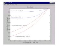
Oh, btw..I found a pic...this is a comparison of exponential vs bessel solution of skin depth at 10K and 20K for a .9mm radius wire, that is approximately a #12 AWG wire. I'll try to find the link, but that eludes me at the moment.
I note the bessel solution has about 1/3 of the exponential solution's effect. Seems the curvature of the wire surface is quite prominent when the exponentially derived skin depth is 1/3 of the radius of the wire.
Cheers, John
Attachments
quickfield seems to be fairly complete for 2-d eddy current simulation, "time-harmonic" and "transient magnetics" simulations can vary conductivity and permeability, transient can model nonlinear permeability but both ignore permitivity-displacement current so it isn't a full E-M simulation
the student version is the first free E/M simulation package i've gotten to do anything remotely plausible without crashes and seizures, i was also able to create my own models and run them with only a few hours of playing with the user interface
cool pictures and most numbers you might want are readily available, time series plotting doesn't appear to include integral results, particularly total current over the cross section of the conductor that would be handy for device terminal characterization in transient mode
their "active field" interface does look like a solution to getting device terminal currents from the transient analysis, examples are given to define problems, control simulations, export and plot with visual basic/word macros - the bored or motivated could probably program a cable simulation to give the current from a sine burst in a transient analysis in a few days, and then explore the effect of magnetic vs non magnetic conductors in minutes
(- I get some credit at work for “evaluating” this software as we really are considering buying it for a funded project, but I don’t think I can sell them on my spending a few days on it – most of this has been off the clock)
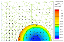
I’ve learned more about how to control meshing (shown) and exploit symmetry, same 2mm cu wire 4mm cntr, 20 KHz current at phase = 0 from harmonic analysis and B field vector plot:
the student version is the first free E/M simulation package i've gotten to do anything remotely plausible without crashes and seizures, i was also able to create my own models and run them with only a few hours of playing with the user interface
cool pictures and most numbers you might want are readily available, time series plotting doesn't appear to include integral results, particularly total current over the cross section of the conductor that would be handy for device terminal characterization in transient mode
their "active field" interface does look like a solution to getting device terminal currents from the transient analysis, examples are given to define problems, control simulations, export and plot with visual basic/word macros - the bored or motivated could probably program a cable simulation to give the current from a sine burst in a transient analysis in a few days, and then explore the effect of magnetic vs non magnetic conductors in minutes
(- I get some credit at work for “evaluating” this software as we really are considering buying it for a funded project, but I don’t think I can sell them on my spending a few days on it – most of this has been off the clock)
I’ve learned more about how to control meshing (shown) and exploit symmetry, same 2mm cu wire 4mm cntr, 20 KHz current at phase = 0 from harmonic analysis and B field vector plot:
Attachments
jcx: I liked the plots..thanks for the effort.
Questions...
Stated zero degrees...what does that mean..the current and mag field vectors appear to be max, which s/b 90 degrees into the sine..
Does this software have the capability of analyzing a linear ramp current of say 10^3 to 10^6 amps per second?
Is it capable of doing a section 90 degrees to the shown plot? IOW, show current density axially? In both the axial, and radial direction?
Can you set a boundary condition on the previously mentioned section, where the material suddenly changes either conductivity or permeability...what I have in mind is viewing the vector components of the eddy currents within the wire..As I suspect that superimposing a uniform current density on a reaction current plot (remember, mag field is linear with distance from center of wire) will produce the same current density as the bessels.
My intent is to simulate a linear ramp, showing the current profile as ramp rate dependent..and, I have a gut feeling that using the typical e/m wave penetration analysis for skin depth is not correct..don't know how to express that yet, but I trust my gut..
It of course, has to fit existing measured results..
I fear no simulation package is capable of doing what I want, and I will be forced to write a whole mess o' code to realize this wish..doable, but it sucks..visual basic ain't exactly the most "tight" with variables, truncation errors have the most "wonderful" characteristics..been bitten by that floating point bug during mag field simulation before.
Oh, BTW...if you increase the frequency to say, 100Mhz or 1000 Mhz...do the reverse rotation magnetic vectors disappear, as well as the negative currents in the middle? When the conductor is fully skinned, current maxwell theory states that there is no internal magnetic field, or current..So, that would be a good test of the simulation software capabilities..
Cheers, John
PS..sorry guys...no really cool picture to put here..maybe somebody else??
Coupla quick notes on that cool plot..
First, notice the arrow mag field vectors? inside the wire, they rotate in the opposite direction to the externals...
That is because inside the middle of the wire, the current is going in the opposite direction..against the current..
As you integrate outward, the magnetic field is flowing cwise. But, at some point, the integral goes to zero , then reverses..The flux direction arrows also reverse as a result..going ccw.
Note that the center of the color fields is moving to the right..that is the effect the opposing current in the partner wire is having on the visible wire..the other wire is causing a magnetic field that is dropping as 1/r in the view, and since it is a field that changes at the same rate as the visible wire one, it will alter the current profile of the visible wire.
What I wish to do is model a linear ramping current with this type of wire model..the reason is this: current skin theory is based on e/m fields impinging on the conductor surface, and driving inwards at some prop speed. So, the classical view is that the sine varying field goes in, showing some exponentially varying drive into the metal..
But, if a linear ramp current of sufficient speed can be modelled using maxwell correctly, I think it will show the exact same internal reaction...that of reversed current direction within the conductor..That would be in direct contradiction to the currently established view of normal to surface wave propagation. But it would certainly validate the metal reaction to the time varying magnetic field, and would force a re-thinking of skin effect in general...(not askin for much, am I??)🙄
Cheers, John
PS.. hittin Bermuda saturday, gonna be back the 27'th..
Hope you guys have solved the unification theory by the time I return...or at least, posted some really cool pictures..In the meantime, I'm really gonna give this topic some deep thought..Yah...right..gonna moped everywhere, and use room service always..
- Home
- General Interest
- Everything Else
- The Skin Game