Hi,
Gracias Sir. I get the picture...😉
If I hadn't refrained from practicing this stuff for the past 20 years or so, I'd dig out Jackson and go solve it myself. But I have, so I can't.
Gracias Sir. I get the picture...😉
As my fellow Bay Area denizen Harry Callahan so correctly observed, "A man's got to know his limitations."
Re: delta
Don't remember, it could be Rhea's book. It's at the library. It's one on the sacred equations I use at work. I have a about 30 possible references, if I had it in electronic form I would post it. I worked out the numbers myself.
Anyways: a couple of figures at 7MHz the skin depth (delta) is about 1 mil (1/1000 inch) at 1 GHz 0.082 mils.
Someone carreied out the whole planewave study and basically at 99% of the current is carried within 5 deltas.
Of course audio people will claim that the remaining 1% is all that matters. 😉
Couple more formulas for dc res in dc or ac case( for copper):
Rdc=(10.37*10^-6 *sigma)/d^2
Rac=1*10^-6*(sqrt(sigma*f)/d)
of course d is assumed to be >> than the skin depth.
(f in hz and d in inches)
1/137 said:grataku ,
how did you arrive at (find?) this formula?
rt
Don't remember, it could be Rhea's book. It's at the library. It's one on the sacred equations I use at work. I have a about 30 possible references, if I had it in electronic form I would post it. I worked out the numbers myself.
Anyways: a couple of figures at 7MHz the skin depth (delta) is about 1 mil (1/1000 inch) at 1 GHz 0.082 mils.
Someone carreied out the whole planewave study and basically at 99% of the current is carried within 5 deltas.
Of course audio people will claim that the remaining 1% is all that matters. 😉
Couple more formulas for dc res in dc or ac case( for copper):
Rdc=(10.37*10^-6 *sigma)/d^2
Rac=1*10^-6*(sqrt(sigma*f)/d)
of course d is assumed to be >> than the skin depth.
(f in hz and d in inches)
Wow..leave for a few days, and see the degenerating stop, and actual equations..Cool
Bessels are needed for wire diameters below about five times skin depth..
Hawksford used steel wire for his test setup....talked all copper throughout, then used steel..
Hawksford had all the energy in the parallel wires travelling within the dielectric as a TEM wave.
He didn't address how the TEM wave was setup, even though it has to get past the wall of the amplifier through two binding posts..Nor, how the energy gets past the speaker binding posts.
Nor, how one can measure the power delivered to a load by using a voltmeter and a current meter.
Also, one would expect an article on skin to cover different frequencies, different conductors, different wire diameters, and stranded vs non stranded. I won't even get into wire geometries..
John Atkinson of Stereo review is supposedly going to make the article available in the archive sections..
Sully
1/137, sully: I think I still have the original, published in that well-refereed </sarcasm> journal "HiFi News and Record Review." And some commentary that followed in The Audio Critic. If you want a copy, I can FAX it to you. If it weren't for that pesky copyright, I'd scan it and post it here...
I don't have the follow-up paper, where Hawksford claims to have measured the effect, but (so I'm told) doesn't provide enough details for replication.
I don't have the follow-up paper, where Hawksford claims to have measured the effect, but (so I'm told) doesn't provide enough details for replication.
Hi,
SY,
Do you mind scanning it nonetheless and e-mail it to the people interested in having a copy?
If it's not too much to ask....we know your limitations and don't mind waiting. 😉
TIA.
SY,
Do you mind scanning it nonetheless and e-mail it to the people interested in having a copy?
If it's not too much to ask....we know your limitations and don't mind waiting. 😉
TIA.
That's an excellent idea, Frank. And it will save me those long-distance phone charges to Belgium. I'll do it from work today, where I've got something better than this ratty 28.8 dial-up I'm stuck with at home.
Just my 2 cents
Just to sum up for dummies like me, I've tried to get back to my old school days. If memory serves, and as Andy_c said, deriving Helmotz equations, or more basically, the curl(H) Maxwell's equation, assuming that the E field solution is in the form :
E(z,t)=Eo.exp(-gamma*z)exp(j*omega*t)
then assuming for good conductors that displacement currents are far less important than conductive ones, the propagation constant is found to be as written on the attached picture (for a semi_infinite medium, not a wire) 😉 .
And if I remember well,it is just a convention to call delta the skin depth. In fact, this depth is the one the field has to travel inside the conductor to be attenuated by a factor e, or exp(1). This does not mean that there is no field after this depth.... So should we go further, or deeper... ?
By the way, I'd like a copy as well !!!
Thanks.
Attachments
I've been talking about the '95 version of the article..it's the one where he claimed to have measured the effect..
Course, using steel with relatively high mu certainly keboshed the actual test..
That fact was glossed over in the paper...It was mentioned, but there was no followup explaining the added internal inductance of the higher mu.
All who attempt to replicate using copper are doomed..It don't work unless you select a good material as a sub, one with mu not equal to one.I've tried three diff ways..to no avail..guess I need some magnetic wire.
Sully
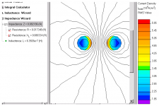
of course armed with little knowledge and free software you could just simulate:
2mm dia Cu conductors, 4mm cntrs, 1 A @20KHz
re 50 Hz values of 0.0119 Ohm R and 0.667 uH ( /m)
(no i won't do requests, download it yourself)
http://www.quickfield.com
2mm dia Cu conductors, 4mm cntrs, 1 A @20KHz
re 50 Hz values of 0.0119 Ohm R and 0.667 uH ( /m)
(no i won't do requests, download it yourself)
http://www.quickfield.com
Attachments
I won't pretend to know much about skin effects, but as far as I can tell, it's been investigated mainly with regard to narrow bandwidth HF currents.
I'm wondering what the net effect is with a typical audio signal. Will significant high frequency components force the low frequencey currents closer to the surface of the conductor, or will those remain evenly distributed?
In other words, does it work as a frequency controlled resistor or a frequency dependent resistor?
Rune
If it were a frequency-dependent resistor then many RF amps using the tank coil for DC supply wouldn't work very well. 😉 So it must be like an odd lossy inductor.
Tim
Tim
runebivrin ""In other words, does it work as a frequency controlled resistor or a frequency dependent resistor?
Yes. the higer the frequency, the lower the resistance. But for typical #12 up conductors, the increase in resistance resulting is awfully low..
Mor importantly, IMHO, is the fact that the inductance of the wire (self, or internal inductance) is frequency dependent. For #18 copper zip, the self inductance is 18% of the overall total..At high frequencies, that number drops to zero.
Grataku ""Can someone that knows please re-state the goal of this thread is? I have lost the point""
What is skin effect?
How does it work?
Is it applicable to audio?
Is Hawksford's paper correct? Did he (accidentally) use a conductor material that matched his simulation?
If a conductor is "charged", meaning it is carrying low frequency current, where the current is evenly distributed within the cross section, and a high frequency transient takes the current to zero, the wire acts as a lower inductance to the hf, but when the current reaches zero, the hf will have discharged a lower inductance. Where did the energy within the wire go? Consumed in current profile re-distribution? Or, does the charged wire react to the hf transient by dumping the energy difference back into the wire end terminal voltage?
To name a few questions coming from this thread.
Sully
- Home
- General Interest
- Everything Else
- The Skin Game