I can't speak to that, but I pulled a trick to effectively make the two run
p-p without degeneration, so what you are listening to is not quite the same.
Sorry, the devil made me do it.
That said, there is nothing wrong with using a CCS, and I have a version
like that here that sounds fine.

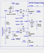
This is the SIT3X output stage. No source resistor degeneration, unless you consider the Schade feedback to be degeneration. But, yes, Schade feedback being a form of local feedback, will introduce its own harmonics.
Attachments
Last edited:
And indeed, I think it's pretty brilliant.
One of the things that influences these decisions is the transconductance
of the SIT vs its Drain impedance and load impedance as well you know.
For a given load, comparing the SIT-1, Big Tokins and Sonys, we can arrive
at different decisions about how much gain to give the biasing element -
CCS, mu follower or complementary follower.
For example with the upcoming Sony parts I ended up with just a CCs
after comparing the alternatives.
I am still struggling to understand just how the SIT3X "Schade feedback" works in the common drain configuration. It is very different from the "ordinary" common source Schade configuration in that the input is referenced to the drain rather than the source, and the feedback behavior is more difficult to understand.
Schade Feedback , patented (?) under that title , can be called "feedback" or it can be called with different names
let's say that Schade Effect is more adequate , simply because we did saw that we can alter and get same or similar transfer characteristic of part in question - in few different ways
in most cases , we are playing with signal on the gate , which is, of course sorta referenced to source
one different way of doing that is - instead of pushing our agenda on gate , we can influence what's happening with source itself - we have SIT introduced in circuit , and its behavior is directly what's influencing source of MOS
so, in short, one way is observing and altering behavior of gate under signal, while other way is pushing and pulling mosfet source ( in all funny ways) while we are fine tuning mosfet gate modulation , to set Mosfet response to action of crazy one
well, if nothing else, I succeeded in complicating things ....... I know what I think, but I'm not so sure that I wrote it clearly

edit: I was certainly funny looking , staring for few days at sim screens, when I realized wakoo nature of DEF OS , where parts are fighting each other , all the way to clipping level ; so, after few days it was sorta clear and simple, but struggle was to crash it to simple level .... practically entire time searching for more plausible complicated explanation
and then thinking entire afternoon how to check that with scope, without unnecessary level of altering circuit nature, and then I found simplest dumbest solution - I already had 0R1 in positive, rail , then I put two more - one in negative rail and one in series with load
comparing sines on these 3 everything was confirmed
sometimes all my simple solutions I have locked in my Blind Spot drawer
let's say that Schade Effect is more adequate , simply because we did saw that we can alter and get same or similar transfer characteristic of part in question - in few different ways
in most cases , we are playing with signal on the gate , which is, of course sorta referenced to source
one different way of doing that is - instead of pushing our agenda on gate , we can influence what's happening with source itself - we have SIT introduced in circuit , and its behavior is directly what's influencing source of MOS
so, in short, one way is observing and altering behavior of gate under signal, while other way is pushing and pulling mosfet source ( in all funny ways) while we are fine tuning mosfet gate modulation , to set Mosfet response to action of crazy one
well, if nothing else, I succeeded in complicating things ....... I know what I think, but I'm not so sure that I wrote it clearly
edit: I was certainly funny looking , staring for few days at sim screens, when I realized wakoo nature of DEF OS , where parts are fighting each other , all the way to clipping level ; so, after few days it was sorta clear and simple, but struggle was to crash it to simple level .... practically entire time searching for more plausible complicated explanation
and then thinking entire afternoon how to check that with scope, without unnecessary level of altering circuit nature, and then I found simplest dumbest solution - I already had 0R1 in positive, rail , then I put two more - one in negative rail and one in series with load
comparing sines on these 3 everything was confirmed
sometimes all my simple solutions I have locked in my Blind Spot drawer
Last edited:
I looked closer at the SIT3X heatsink requirements and what the diyAudio Deluxe 5U Aluminum chassis heatsinks can handle and it looks like no changes would required to use that chassis.
It my understanding of those heatsink specifications, the heatsinks on each side have a C/W factor of 0.14C/W. For a temperature rise of 25C, that would allow 178W per channel into the heatsinks. With 1.8A bias, that allows rail voltages of over 49V each, which is greater than the 44V I currently see.
If there is enough interest, I can do a new run of PCBs and make them and the BOMs available.
The SIT3X P6 pot adjustment parameter A has a circuit similarity to "Schade feedback" but it can also be considered as an attenuation parameter to the input to the gate of the PFET. The circuit analysis rather complicated, and have not yet been able to find a simple math description of the behavior.
In both simulation and the actual build, very small changes to the A value of the P6 pot cause major changes to the relative AC currents of the SIT and PFET. I find a similarity to the P3 pot of the FirstWatt F5 V2. The P3 pot modifies the relative loop gains of the top and bottom FET loops. With very small changes to the P3 pot the 2nd harmonic can be adjusted over a wide range. Very curious.
In both simulation and the actual build, very small changes to the A value of the P6 pot cause major changes to the relative AC currents of the SIT and PFET. I find a similarity to the P3 pot of the FirstWatt F5 V2. The P3 pot modifies the relative loop gains of the top and bottom FET loops. With very small changes to the P3 pot the 2nd harmonic can be adjusted over a wide range. Very curious.
go figure
for eons, constructrors were searching for symmetry in push-pull stages, and I've read of just recent (well, recent-from human perspective and - well, far from me reading it all 🙂 ) thinking in opposite direction - deliberate move from symmetry, always with goal of getting that nice SET THD Spectra, more or less
remember first time seeing article in Sound Practices - (Issue 8, p.36, "Ultimate - by Rickard Berglund, Sweden"), where he deliberately made one half of OS having just 50% of modulation, vs. other half, and made entire list of measurements with various tubes used
then I remember seeing sch of some NAD amplifier ( maybe even receiver or something) where in OS they've put one BJT and one mosfet
then, of course , Papa's SUSY - everything about symmetry, and he resorted in last period on controlled spoiling of the same , and he even coined a name, (only to deny it, to puzzle poor ZM even further) Utrasymmetry
Ultra probably being code name for Tongue-in-cheek
(Boy, was I happy with spoiling my Babelfish Aleph XJ modulation of Aleph CCS-es!)
anyway, get this not as try of explanation (far from it!), just as me throwing more info on pile, so we can be even more puzzled together 🙂
dunno - maybe we can't understand all of it, more likely that we can research and catalog what we're getting , then exploit most satisfactory examples
and , we shall not forget what Pa said - "Snatch them while you can"
Attachments
I looked ...
If there is enough interest, I can do a new run of PCBs and make them and the BOMs available.
Yes! very well documented & interesting design
then, of course , Papa's SUSY - everything about symmetry, and he resorted in last period on controlled spoiling of the same , and he even coined a name, (only to deny it, to puzzle poor ZM even further) Utrasymmetry
Ultra probably being code name for Tongue-in-cheek[/I]
A physicist would say it was properly referred to as "Broken Symmetry"
😛

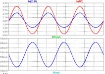
And what did you see in the 3 scope traces? Did you see the waveforms in the plots below, where the FETs are fighting each other, but the PFET is the stronger and defines the polarity of the current into Rload.
Schade Feedback ...
edit: I was certainly funny looking , staring for few days at sim screens, when I realized wakoo nature of DEF OS , where parts are fighting each other , all the way to clipping level ; so, after few days it was sorta clear and simple, but struggle was to crash it to simple level .... practically entire time searching for more plausible complicated explanation
and then thinking entire afternoon how to check that with scope, without unnecessary level of altering circuit nature, and then I found simplest dumbest solution - I already had 0R1 in positive, rail , then I put two more - one in negative rail and one in series with load
comparing sines on these 3 everything was confirmed
sometimes all my simple solutions I have locked in my Blind Spot drawer
Attachments
yes, exactly that - fighting, antiphase
posts #190 and #195 , and later ones
Most Greedy Boy, of them all... or (there is no) DEFiSIT of Papa's Koans
posts #190 and #195 , and later ones
Most Greedy Boy, of them all... or (there is no) DEFiSIT of Papa's Koans
Do you suppose that is the behavior of the production SIT-3 amps?
yes, exactly that - fighting, antiphase
posts #190 and #195 , and later ones
Most Greedy Boy, of them all... or (there is no) DEFiSIT of Papa's Koans
Wacko -voodoo ...
And, yes, with the P6 pot A=1 that is the behavior of the SIT3X, but the distortion is much higher than when operating in the "normal" push-pull region. The harmonic falloff rate is about the same at -15dB per harmonic.
And, yes, with the P6 pot A=1 that is the behavior of the SIT3X, but the distortion is much higher than when operating in the "normal" push-pull region. The harmonic falloff rate is about the same at -15dB per harmonic.
Attachments

Last edited:
- Home
- Amplifiers
- Pass Labs
- The SIT-3X Amplifier