I am slowly making progress on the SIT3X build and am ready to bench test the first channel. Here are some images.
Looks good!
Request which maybe possible, could you make the board connector with a male/female 90 degree connector like for instance here...
GB Pass SONY VFET Version 2 - AL Boards by Tea-Bag
Looks good!
Request which maybe possible, could you make the board connector with a male/female 90 degree connector like for instance here...
GB Pass SONY VFET Version 2 - AL Boards by Tea-Bag
That is probably a good idea. If I do a PCB revision I will consider it. The only downside is that it requires the OS and FE boards to be mounted together. With the ribbon cable, the FE boards can be some distance away if the packaging design makes that either necessary or otherwise desirable.
That is probably a good idea. If I do a PCB revision I will consider it. The only downside is that it requires the OS and FE boards to be mounted together. With the ribbon cable, the FE boards can be some distance away if the packaging design makes that either necessary or otherwise desirable.
Thanks, either way is ok
I am not sure that all of the low amplitude "oscillation" I am seeing is actually due to the FE circuit, since much of it appears to be at the switching regulator frequency of my bench power supplies.
Yes, the gate stoppers are important. I added 1K resistors Rgs34 in series with the Q3&Q4 bases and the "oscillation" was reduced. I will push ahead with the moving on to testing the output stage using the FE as modified.
Yes, the gate stoppers are important. I added 1K resistors Rgs34 in series with the Q3&Q4 bases and the "oscillation" was reduced. I will push ahead with the moving on to testing the output stage using the FE as modified.
I have seen this before, last time in some examples of the cascoded F5 turbo.
Nothing seemed to work except some resistance between the Jfet Drains and
the Emitters of the cascodes.
That said, Base stoppers might do as well here.

Nothing seemed to work except some resistance between the Jfet Drains and
the Emitters of the cascodes.
That said, Base stoppers might do as well here.
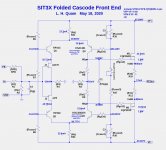
SIT3X update
Good news. The "oscillation" problems I previously reported were due the my switching regulated power supplies that I was using for initial debugging and adjustment of the bias currents.
I found a PCB layout error in the folded cascode front-end (FCFE) PCB, a pin assignment error for the TL431 on the output-stage PCB, and a resistor that needed to be changed in the OS optocoupler circuit to obtain proper bias adjustment.
With these corrections the SIT3X is functioning close to expectations, but some modifications to the FCFE are still required to eliminate clipping above about 25W output into 8R.
At 1W 1kHz into 8R I see 0.011% THD.
The capacitance multiplier is working very well. The 60Hz and higher harmonics are below my spectrum analyzer measurement limits. I accidentally damaged the IRFP240 FET in the capacitance multiplier, causing the source-to-drain resistance to become 16R, which totally defeated the capacitance multiplier, resulting in 120mVrms between the SIT drain ground and high 60Hz harmonics at amplifier output. The capacitance multiplier is both necessary and effective.
I will post some measurements soon.
For some reason the ANTEK AN-10435 toroid transformer is buzzing at a level I have not previously seen with essentially the same power supply topology.
With no load on the power supply the buzz/hum is gone. With a single channel connected at 1.8A bias and +/-45V PS output voltages I obtain bad mechanical buzzing.
Another weirdness is that my Klein AC ammeter show a current into the transformer being 2.96A AC when a single SIT3X channel is connected with 1.8A bias. The implies 2.96A*120V=355VA input and 1.8A*90V=162W load. The Klein AC ammeter probably is not making proper measurement when the PS rectifier load consists of high current pulses, but similar measurements of other amplifiers with a similar power supply design do not show such a disparity of input VA vs. load Watts.
Is the toroid buzz caused by a bad transformer or due to core saturation by the high current pulses?
I ran into that once. I believe it was a bad cap/PSU trace in my instance. I’ll be curious to hear what it ends up being in your case.
I found the problem with the buzzing toroid transformer. It was a stupid mistake forgetting 2 jumper wires on the power supply rectfier/capacitor boards, causing 1/2 of the rectifier bridge to be unconnected. All is well with the jumper wires added.
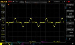
Below is the AC voltage waveform across a 0R0625 (0R25/4) resistor in series with the power-line neutral wire. The AC current is 16X the voltage shown. Thus, -.880mV minimum of the negative pulse corresponds to -14A.
Below is the AC voltage waveform across a 0R0625 (0R25/4) resistor in series with the power-line neutral wire. The AC current is 16X the voltage shown. Thus, -.880mV minimum of the negative pulse corresponds to -14A.
Attachments
frankly, I'm Happy Camper when I see that my bench stupidity is in case, and I wasn't so stupid while drawing on back of napkin 🙂

oh yeah, when Absolute Dodossness is in the case, nobody can compete with me .... still able to make greenhorn mistakes, while years of experience gave that I'm making them without feeling guilty

Regarding post #194:
This looks like an opportunity to investigate the performance of an LT4320 based synchronous rectifier. I would suggest trying the IPP034NE7N3 G Mosfets. This should spread out the charging pulses significantly and improve efficiency of energy transfer.
This looks like an opportunity to investigate the performance of an LT4320 based synchronous rectifier. I would suggest trying the IPP034NE7N3 G Mosfets. This should spread out the charging pulses significantly and improve efficiency of energy transfer.
The LT4320 “file test” video at The Dreaded "File Test" on an LT4320 Ideal Diode Bridge Controller | Analog Devices - very impressive!
Does this approach have lower switching noise relative to other diode types and is a snubber still required for best performance?
Does this approach have lower switching noise relative to other diode types and is a snubber still required for best performance?
Last edited:
The use of the LT4320 controller does not completely eliminate current pulses which may "ring the bell" of the transformer secondary winding, but it does reduce their intensity. The LT4320 based PCBs that I have used so far have places for CX, CS and RS components on the AC side. The DC output side also has locations for small and larger bypass caps. The small 0.01uF to 0.10uF caps are there for the internal oscillator of LT4320. (It must use a charge pump to generate the higher gate control voltage for the output Mosfets.) A larger cap from 10uF to 1000uF may also be added in parallel with the bulk capacitance that will act as the main smoothing and energy storage reservoir.
- Home
- Amplifiers
- Pass Labs
- The SIT-3X Amplifier