Only 6. 😉
If I understand the 2SK182ES mu-follower measurements correctly, the implication is that a higher supply voltage may be necessary to obtain more optimum operation of the devices in or near their "sweet spot." I have a pair of Plitron 625VA, 50V transformers set aside to build a pair of Singing Bush monoblocks. Maximum unloaded voltage would be 70 VDC, but I plan to build a PSU which would arrive at ~ 65 VDC with a couple volts of adjustment. Tentatively this looks like FERD diode bridge -> 36,000 uF -> MrEvil CapMx -> 36,000 uF.
Ok so far? Suggestions?
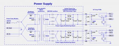
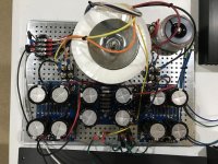
I am running my amplifier SIT measurements, Mu Follower, and amplifier build with an Antek AN8475 transformer: 800VAC, 2 x 75VAC secondary windings, resulting in a pair of 94VDC supplies.
Attachments
That's pretty hard core.
I may still be able to get there with the Plitron toroids that I already have. Their dual secondary windings can be wired in series for 100 VAC. Then a choke input filter could be used to get about 90 VDC. My 36,000 uF caps are KEMET ALS70 series, rated at 100 VDC. They should be good for the duty, as long as the swinging choke filter is always under load. Those caps probably wouldn't like 140V very much.
Thinking either a Hammond 193V or 195T5 choke, same as the ones I'm using in my big MoFos.
See post SIT measurements, Mu Follower, and amplifier build. For my six 2SK182ES SITs, a rough approximation of th operating point is:
Vd = K*Ibias*(1+PPR)
PPR = IpullupAC/IpulldownAC. PPR=0 when the mu-follower is a constant current source.
K is approximately 3.3*RloadSS, where RloadSS is the output load impedance at the amplifier sweet-spot, which typically choose to be 6 Ohms, resulting in K=20.
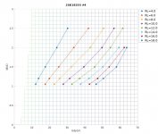
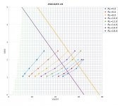
Below is a plot of the sweet-spot curves for my SIT#4.
If you want the amplifier to have roughly the same harmonic constant with 4R and 8R loads, the sweet-spot load impedance RloadSS should be near 6R (half way between 4R and 8R). This will also result in the 2nd harmonics to have opposite phases at 4R and 8R.
Choose RL = RloadSS*(1+PPR).
Thus for RloadSS=6R and PPR=0 (CCS), choose a sweetspot point on the RL=6 (Red) curve.
For RloadSS=6R and PPR=1.33, choose a sweetspot point on the RL=8 (Yellow) curve.
From the above choice, your power supply voltage requirement will be:
Vrail > Vd+sqrt(2*Rload*Wattsmax)
Alternatively:
Wattsmax < (Vrail-Vd)^2/(2*Rload)
Vd = K*Ibias*(1+PPR)
PPR = IpullupAC/IpulldownAC. PPR=0 when the mu-follower is a constant current source.
K is approximately 3.3*RloadSS, where RloadSS is the output load impedance at the amplifier sweet-spot, which typically choose to be 6 Ohms, resulting in K=20.
Below is a plot of the sweet-spot curves for my SIT#4.
If you want the amplifier to have roughly the same harmonic constant with 4R and 8R loads, the sweet-spot load impedance RloadSS should be near 6R (half way between 4R and 8R). This will also result in the 2nd harmonics to have opposite phases at 4R and 8R.
Choose RL = RloadSS*(1+PPR).
Thus for RloadSS=6R and PPR=0 (CCS), choose a sweetspot point on the RL=6 (Red) curve.
For RloadSS=6R and PPR=1.33, choose a sweetspot point on the RL=8 (Yellow) curve.
From the above choice, your power supply voltage requirement will be:
Vrail > Vd+sqrt(2*Rload*Wattsmax)
Alternatively:
Wattsmax < (Vrail-Vd)^2/(2*Rload)
Attachments
Really fascinating stuff..
Looks like the yellow curve best represents my sweetspot. With Id from 2.0 to 2.5 Amps, this will keep heat manageable in the monoblock chassis. The 193V choke is suitable for the power supply, swinging choke configuration.
Looks like the yellow curve best represents my sweetspot. With Id from 2.0 to 2.5 Amps, this will keep heat manageable in the monoblock chassis. The 193V choke is suitable for the power supply, swinging choke configuration.
This will also result in the 2nd harmonics to have opposite phases at 4R and 8R.
Wouldn’t we want it the same phase from 4 and up?
Many loudspeakers have impedance curves that are from 4 to 10 ohms.
Thanks
Wouldn’t we want it the same phase from 4 and up?
Many loudspeakers have impedance curves that are from 4 to 10 ohms.
Thanks
You could minimise H2 at 4R, and then would H2 keep the same phase, but increase from 4R up to 10R and become significantly larger than if you minimize it at 6R. The adjustment knob on the FirstWatt SIT-1 allows you to choose to make that choice.
The swinging choke LC filter on 100 VAC seems to be the way to go. A low dropout active filter (MrEvil CapMx) followed by another bulk capacitor would allow adjustable rail voltage at the amp boards.
Now we need to look at the rest of the Singing Bush board circuits to see if they can handle the higher voltage.
@ZM, thoughts?
Now we need to look at the rest of the Singing Bush board circuits to see if they can handle the higher voltage.
@ZM, thoughts?
no problem with higher voltage
output cap voltage major change , same as few resistor values changed , but nothing major
Mu part - R1 need to be increased (ref. post #3)
SIT gain part - R2/R3 string , bigger heatsink on IRF, maybe some twiddle with R11 value, if pre-set range for setting Ugs isn't adequate to cover for your desired working point (ref. post #4)
so, piece of cake
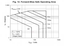
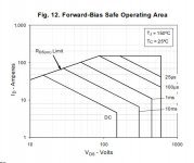
Yesterday to destroyed an IXYS IXFN140N30P puck at powerup of my amp, which was biased for 2.5A with 84V rails. I believe the problem was due to the time constant being too long in the SIT bias circuit and exceeding the DC safe-operating-area (SOA) of the IXFN140N30P. I reduced the electrolytic cap from 1mF to 220uF, and hope that helps. I will also cut back the bias current to 2A or less. I will replace the IXFN140N30P with an IXFN48N60P whose SOA should be be more forgiving.
I'd check the protection zener on the MOSFET, if that goes open circuit the device is very vulnerable.
Haven't heard of that before. This bodes for an interesting development.Yesterday to destroyed an IXYS IXFN140N30P puck at powerup of my amp...
I'm currently working on a revised PSU that won't destroy its capacitors or regulator on powerup.
Yes. On startup the SIT J1 Vgs is 0, Vds is 0 and the MOSFET M1 Vds is 94V. The time constant for the M1 bias circuit is shorter than than that of the J1 bias circuit, therefore M1 goes to 2.5A well before J1 Vgs begins to turn off J1. Red dot, or slightly further to the right.So you are saying that your startup put you where the red dot is?
well, I'm sure that I had tons of powering up/down cycles ...... rail being 60Vdc under load and some above 70Vdc while thingie biasing up during power on
puck as per Pa's recipe, IXFN140N20P,which is having SOA practically stopping at 50Vdc, even if lowest current figure there is 10A
damn thingie behaved, so I practically forgot everything about SOA, even if I was looking and thinking about it,comparing at least dozen of pucks, before hand
anyway, to cut a story short, it seems I can trust said type in these circumstances, but we can see now that for higher rails we must search for another, trusty, candidate -which can be used for various approaches
though, with Singing Bush , biasing for SIT is faster than Mu starts conducting , which leads to behavior that Mu is gradually rising Iq and getting same gradually decreasing voltage
sorta contrary to lhquam's circuit, as he explained it
Last edited:

The IXYS IXFN64N60P has a good SOA and looks ok otherwise. See the datasheet at http://ixapps.ixys.com/DataSheet/99443.pdf.
Attachments
- Home
- Amplifiers
- Pass Labs
- The Singing Bush