In stock at Mouser and reasonably priced, for hockey pucks.
Win - win
I may have to build a separate BA2015 Schade amp to use the others.
Win - win
I may have to build a separate BA2015 Schade amp to use the others.
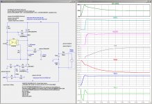
Here is one channel’s power supply...
I like the look of those rectifiers, what are you using?
Here is a simulation of the startup of my amplifier. I will try to verify this with single-trace scope bench tests. The two most important waveforms are Vds(M1) and Id(M1). Unfortunately I do not have a good way to measure Id(M1), or Id(J1). However I can measure the voltage across the 4R7 100W resistor between V- and Gnd.
Attachments
there is no pinch of doubt in fact that's useful to know what's happening in amplifier in any particular moment
though, I believe that most effective and elegant solution is simply using that puck you found yesterday (for amp with elevated rail, closer to 100V) and making an amp with best sound in mind, counting on fact that parts used are durable enough to cover transition changes
I hate to think about fact what can happen with part in rare occasion of dangling full output swing, if I'm using part sensitive enough that I must care about Big BadaBoom
Hi Zen Mod,
I assume there is no special requirements to the SIT's selection as they are use as singles?
Cheers,
Mogens
I assume there is no special requirements to the SIT's selection as they are use as singles?
Cheers,
Mogens
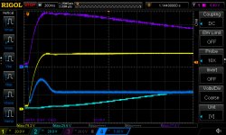
Here are some startup waveforms corresponding to the circuit in post #406. The horizontal scale is .2s/div.
- violet is Vds(M1) at 20V/div
- yellow is V+ at 20V/div
- blue is V- at 5V/div
- cyan is Vs(M1) (M1 source pin) at 20V/div
- Vd(J1) is slightly less than Vs(M1).
Attachments
Hi Zen Mod,
I assume there is no special requirements to the SIT's selection as they are use as singles?
Cheers,
Mogens
I did wrote about that few times,all tests are showing that having them so-so matched can't harm, resulting in similar THD Spectra between channels
Here are some startup waveforms corresponding to the circuit in post #406. The horizontal scale is .2s/div.
The simulation in post #406 agree fairly well with these measurements.
- violet is Vds(M1) at 20V/div
- yellow is V+ at 20V/div
- blue is V- at 5V/div
- cyan is Vs(M1) (M1 source pin) at 20V/div
- Vd(J1) is slightly less than Vs(M1).
tnx lhquam
and tnx for special Singing Bush picture you sent me in e-mail 🙂
regarding Singing Bush - as I already described - SIT biasing circuit is faster than Mu, so during startup procedure SIT is already biased in moment when Mu is starting conduction ........ so Mu is seeing (almost ) full rail voltage while current being 0 ...... then as current is rising, Mu Puck Vds is decreasing........
so , highest Vds is (almost) rail voltage , while highest current is pre-set Iq, luckily ( 'twas a Cunning Plan) never happening in same time 🙂
Last edited:
Yes, that is a big advantage with having a separate power supply for the SIT bias circuit. I strongly considered that when designing my PCBs, and would do it for future designs.
I just looked at my PCB artwork and at trivial mod, cutting one trace and adding a wire to an unused Molex connector pin would allow using a separate supply for V-. The only other change would be to reduce one cap in the bias circuit from 1mF to around 22uF.
I just looked at my PCB artwork and at trivial mod, cutting one trace and adding a wire to an unused Molex connector pin would allow using a separate supply for V-. The only other change would be to reduce one cap in the bias circuit from 1mF to around 22uF.
Last edited:
ZM and other builders of the Singing Bush:
Does anyone have definitive listening opinions. What combinations of the mu follower resistors are preferred? (I refer the the resistors as Rmu (gain) and Rhi (the resistor above Rmu), where Rmu+Rhi defines the overall bias current.)
I have done some A/B listening comparisons against my XA25 build. The SIT amp is currently at 2.0A, Rmu=0R15, Rhi=0R5. Both amplifiers have an excellent sound stage. The main difference I hear is probably due to low damping factor, where I hear some low frequency "boom", probably due to speaker resonances. It is amazing that a 1%+ THD amplifier competes well against one with 100X lower THD.
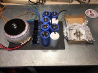
And now for something completely different, a man building a Singing Bush.
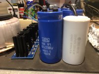
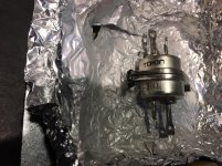
Power supply mock up, and matched SIT's.
Upgraded my Klipsch Heresy 2 speakers with new crossovers from Crities along with titanium dome tweeters from series 3 & 4. Once inside, fiberglass insulation was added, the cabinet was empty(?). Very nice sounding with my ACA mono-blocks.
Next, test SIT's using Zen Mod method, need to drill and tap a couple of holes to mount the SIT on a heat sink.
I hope to be very ready when the world wakes from it's nap.
Attachments
ZM and other builders of the Singing Bush:
Does anyone have definitive listening opinions. What combinations of the mu follower resistors are preferred? (I refer the the resistors as Rmu (gain) and Rhi (the resistor above Rmu), where Rmu+Rhi defines the overall bias current.)
I have done some A/B listening comparisons against my XA25 build. The SIT amp is currently at 2.0A, Rmu=0R15, Rhi=0R5. Both amplifiers have an excellent sound stage. The main difference I hear is probably due to low damping factor, where I hear some low frequency "boom", probably due to speaker resonances. It is amazing that a 1%+ THD amplifier competes well against one with 100X lower THD.
Thank you for all your work.
My build was based on the 50W Single-Ended BAF2015 2SK77B amp, with the THF-51S in place of the 2SK77B.
So it started out with Rhi=0R2 and Rmu=0R2, at 3.3A. It sounded quite good at lower volume but became harsh at higher volume. Since I usually listened at lower volume, I enjoyed it for some time. Another thing I noticed was that the sound projected out more than usual. This was also more pronounced at higher volume. Reversing the speaker connection polarity changed that to the sound being more behind the speakers.
After I did some distortion measurements, I found that the distortion was quite high. I then realized that was why the sound was harsh at higher listening levels.
After reading Zen Mod's Singing Bush posts, I changed Rhi to 0R3 (ZM had 0R4), and left Rmu at 0R2, and I=2,54A. The result was a drastic reduction in distortion. At this point, the amplifier was now also very enjoyable at higher volume. I still preferred the reversed polarity of the speaker connection for negative phase H2. Another characteristic of the amplifier, both before and after the Rhi change, was that the image projected was tighter and more focused than that of my other amplifiers.
I am quite happy with the sound right now so I haven't tried other combinations of Rhi and Rmu. Perhaps I will experiment when the weather gets warmer and I take the amps out of service and run one of my cooler (relatively speaking) amps.
As for comparisons, I have a SissySIT, 2SJ28 Hammond choke loaded L'Amp, and diyAudio Sony VFET amp. I like this BAF2015 amp best as it seems to me to give the more realistic portrayal of music. The other amps are still great amps - it's just that I prefer this amp more.
Some distortion measurements:
The Singing Bush
The first measurement was of Rhi=Rmu=0R2. The rest were for Rhi=0R3 Rmu=0R2
ZM - Transformer has 2X 48v, 18v, 12v secondaries. 18v for bias circuit?
18Vac perfect
if you have separate winding on Big Donut, that's practically the same as having separate small Donut

- Home
- Amplifiers
- Pass Labs
- The Singing Bush