The way I look at it, having an unmatched pair of SITs is way better than having no SITs at all.
An unmatched pair may measure a bit differently but there may not be a noticeable difference in sound.
Of all my SITs, and I purchased them unmatched in pairs, one pair actually were closely matched when distortion was measured in the finished amp. The other pairs had up to 100% difference in distortion between channels. It doesn't bother me. I just enjoy the music.
Just build and enjoy! 🙂

I have a matched quad of the THF-51s and two just roughly matched pairs.
It is my intention just to use one of the roughly matched pairs for the "Lazy Bush".
I can see how it performs. It should be quite easy to change to another device. Only one device on a large heat sink should make it easy to change to another.
It is my intention just to use one of the roughly matched pairs for the "Lazy Bush".
I can see how it performs. It should be quite easy to change to another device. Only one device on a large heat sink should make it easy to change to another.
I agree with Ben Mah. Measured numbers are one thing, but listening reality is another. I have built several SIT amps, and none of my SITs were matched, so the measurements vary but after listening, I can't be bothered to change out any devices. I try to bias for similar distortion profiles and leave it at that.
I just enjoy the music.
Just build and enjoy! 🙂
Yea, thats not a bad idea at all.
My take on it is that the ONLY thing that really counts, for me, nowdays, is the total playback systems ability to deliver a really engaging and present musical experience.
And, my take on the building experience: Take it very easy, and extra slowly, truely enjoy every single part of the builds🙂🤚
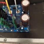
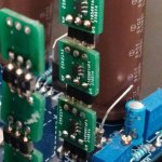
Glowing again! I finally had time to diagnose my left Singing Bush monoblock. If you all remember I had an issue of flipping a cap to the wrong polarity on the SIT board during assembly. Turns out that wasn’t the only issue or the actual issue at the end of the day. After replacing the suspect capacitor the channel seemed to work for a while, although I was only able to bias the input stage to about 11mV. About a week later the channel lost sound completely. ZM and I suspected the reversed cap may have done some damage to the 2sk2145’s. So this week I went about matching 6 more from my stash, anticipating replacing them. I removed the old 2sk’s from the board but figured I would throw them in to my matching jig just to see if they did appear damaged or dead. Nope! They all came up to their previous Idss’s. As I was removing them I did notice they popped off the board rather easily. So the first issue was that the 2sk’s were not making great contact with their pads. I soldered the old bugs back on and retouched all of my solder joints for good measure. Viola! The board biased right up to 20mV. First issue solved!
Then I went through the start up procedure on that channel again. For some reason I couldn’t get the voltage off the SIT to come up over 15-16V…. Unless I wiggled some wires around. Clearly I had an intermittent contact issue somewhere. I went over all my grounds, resoldered all the wired connections between the boards, and wire brushed the contact points on the SIT itself before hooking everything back up. That did it! Flipping the switch I was able to get up to 34V at 425mV bias. P1 on the MU runs out of adjustment at that point. Close enough for me. Both channels are pretty much silent. Running them with a Yarra preamp with the Haikun gain stage. Sound is phenomenal. I missed these so much and regret staring at them in my listening for the last year. Time for more listening!
Then I went through the start up procedure on that channel again. For some reason I couldn’t get the voltage off the SIT to come up over 15-16V…. Unless I wiggled some wires around. Clearly I had an intermittent contact issue somewhere. I went over all my grounds, resoldered all the wired connections between the boards, and wire brushed the contact points on the SIT itself before hooking everything back up. That did it! Flipping the switch I was able to get up to 34V at 425mV bias. P1 on the MU runs out of adjustment at that point. Close enough for me. Both channels are pretty much silent. Running them with a Yarra preamp with the Haikun gain stage. Sound is phenomenal. I missed these so much and regret staring at them in my listening for the last year. Time for more listening!
heck
2SK2145 gone easily from pcb because they're soldered with proper solder, so you really needed just some regular heat
proper means - old fashioned, lead based
I'm checking each 2145 with ohmmeter, after hot air cycle

in any case, glad that you solved it

2SK2145 gone easily from pcb because they're soldered with proper solder, so you really needed just some regular heat
proper means - old fashioned, lead based
I'm checking each 2145 with ohmmeter, after hot air cycle
in any case, glad that you solved it
Thanks ZM! You’re right. I never gave them enough hot air when I soldered them the first time. My fault. I’m always afraid to melt those little guys. Now I know they can handle a little heat. 😈
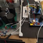
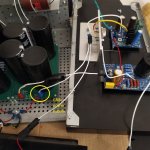
My growing family. 😉

My growing family. 😉
greeting ZenMod and all friends.
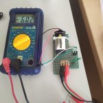
i am testing the bush i replicated. I hit my head on a problem that I can't figure out: I can't set the current produced by the jfet. The digital tester does not measure anything, it stays at zero. The LEDs light up. I detect 28 ohm on R9 (which is in parallel with trimmer P1). The voltage of 64V DC is present.
I try to move P1, and nothing happens. As if the fets were banned or dead (but I don't think so, because I replaced them with 2145 in my possession which are certainly good).
I need help getting out of it. ZenMod will you be able to save me?
sorry I meant that I measured on R8 (28 ohm at start)
R9 measures 1 Ohm; performing the mV measurement on R9 I get nothing on the tester, it remains at zero
R9 measures 1 Ohm; performing the mV measurement on R9 I get nothing on the tester, it remains at zero


what voltage you have at G of JFets?
you must have present high rail, approx. +8V at IRF Source, few V negative at JFet gates
and that last one must vary with P2
I hope you did connect GND to pcb too
you must have present high rail, approx. +8V at IRF Source, few V negative at JFet gates
and that last one must vary with P2
I hope you did connect GND to pcb too
- what voltage you have at G of JFets? On G (gate) of fets -4.16V in the upper ones and -11volt in the lower ones of the scheme( +7,4 on drain Up , -3,7 drain for inferior fets )
+8V at IRF Source, I detect on the source of the IRF +11
and that last one must vary with P2 , no it doesn't vary
On G of the SIT I detect -3.65V and it tends to vary moving P2
- I hope you did connect GND to pcb too - I don't think I could make measurements without reference to GND
+8V at IRF Source, I detect on the source of the IRF +11
and that last one must vary with P2 , no it doesn't vary
On G of the SIT I detect -3.65V and it tends to vary moving P2
- I hope you did connect GND to pcb too - I don't think I could make measurements without reference to GND
Attachments
something is fishy with JFets you installed
checking on my list - you got pcbs with JFets already soldered; what did happen to them?
checking on my list - you got pcbs with JFets already soldered; what did happen to them?
I reported earlier that the exact same behavior occurred with the fets installed by you. I can safely reassemble them, I have no problems. I took them apart because I thought they were broken
schematic is proven, pcb is proven
just in case - pinout of your adapter boards is proven?
is there -12V at output of LM317?
just in case - pinout of your adapter boards is proven?
is there -12V at output of LM317?
- Home
- Amplifiers
- Pass Labs
- The Singing Bush Tips 'n' Tricks