perhaps the 317 is the defendant: on its central out pin I don't detect 12v: I detected with the DMM connected to the GND of the P.Supply and the positive on the central out pin = ZERO.
On the input pin of the 317 I read 9V: this puzzles me.
In AC I detect 16 V before the rectifier bridge
On the input pin of the 317 I read 9V: this puzzles me.
In AC I detect 16 V before the rectifier bridge
LM 317 pinout is - numbers to you, pins down : most left Adjust, mid out, most right input
all ref to GND:
on input you must see close to your Aux AC*1.41; if you have 15Vac there, DC must be close to -20Vdc
of course, worth repeating, that Aux (15Vac) must be independent/floating of main audio PSU secondary
so, confirm that you have proper Aux AC voltage, then if anything is fishy with LM317 voltages, replace it
Pinout 317 comes back to me
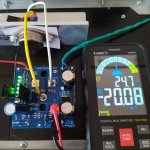
I confirm 16 V AC input. On the positive of the bridge I detect 8.8v DC !! (reference the negative pin of the bridge itself). this value doesn't add up: it should be 19v
I confirm 16 V AC input. On the positive of the bridge I detect 8.8v DC !! (reference the negative pin of the bridge itself). this value doesn't add up: it should be 19v
317 replaced. I am detecting 12v on its output. fet bias retried. I don't detect anything on R8.
Abandonment if there are no other ideas
Abandonment if there are no other ideas

the preliminary checks carried out before assembling the components do not always give us back the truth. I discovered the component responsible for the problem after examining it several times and found it suitable, I set it aside. It was the R8 which, checked again today with another tester, did not return any value: it was the faulty one and also interrupted the circuit in its position. I happily replaced it on the fly and of course was able to bias the buffer to 20mA. Finally the first step is done. Obviously if I had sensed that resistance was about to die I would not have tried frantically to shoot into the pile...and despite the shots no one fell...I was swollen with rage that was the engine to control everything again. I hope I don't have any more problems. Everything went smoothly in the previous construction of the Bush.
I thank ZenMod who generously helped me: I'm leaving again also thanks to your support
I thank ZenMod who generously helped me: I'm leaving again also thanks to your support
Attachments

well, even if you didn't had R8 at all, there should be current path through P1, if properly set
not that I'll like 20mA through puny trimpot, but it'll work
anyhow, I'm glad it works now
not that I'll like 20mA through puny trimpot, but it'll work
anyhow, I'm glad it works now
Thanks ZM, I really appreciate your help.
The R8 has been replaced, it was the only quick way to be able to measure and implicitly realize that the circuit was fine. Above all, now I know that I haven't become an idiot yet... I have to think about it at 68 years old
The R8 has been replaced, it was the only quick way to be able to measure and implicitly realize that the circuit was fine. Above all, now I know that I haven't become an idiot yet... I have to think about it at 68 years old
well, I did found remedy for that problem many moons ago
realized how big idiot I am, then I could proceed without that burden

realized how big idiot I am, then I could proceed without that burden
being an idiot is helpful thing - ppl really nothing expecting from you
but then, what I know, I also know that I could never be a Surgeon , as some are
that is A Craft, and that is A Responsibility
but then, what I know, I also know that I could never be a Surgeon , as some are
that is A Craft, and that is A Responsibility
biased the power section. Obtaining it was not easy: I had to change the values of two Resistors.
The first on the MU board R3 increased from 100 to 150 R. The other on the SIT board, R11 increased from 1k5 to 3k3.
So I was able to get the design values: 460mV for Iq and the potential of 37V on the drain of the SIT (2SK180). Good progress. Tomorrow I fight with the other channel
The first on the MU board R3 increased from 100 to 150 R. The other on the SIT board, R11 increased from 1k5 to 3k3.
So I was able to get the design values: 460mV for Iq and the potential of 37V on the drain of the SIT (2SK180). Good progress. Tomorrow I fight with the other channel
Attachments

bias OK for the other channel as well.
In this case I had to increase R11 to 2k7 on the MU board and increase R3 on the SIT board to 220R.
Very good.
Even with an initial block that confused me a bit (the cursed R8 ) everything works according to the directive of Maestro ZM to whom I pay my respects
In this case I had to increase R11 to 2k7 on the MU board and increase R3 on the SIT board to 220R.
Very good.
Even with an initial block that confused me a bit (the cursed R8 ) everything works according to the directive of Maestro ZM to whom I pay my respects

Great Zen Mod, the new Bush is playing. Wonderful as always: the magic of this amp repeats itself. Forget the hitches of the initial tests, now the Music and what Music.
A lot of gratitude for the help you have always given to everyone, not only to me, but above all for having given us this incredible amp.
A lot of gratitude for the help you have always given to everyone, not only to me, but above all for having given us this incredible amp.
Attachments


I have a weird situation... I don't see any voltage gain, and in fact I get fewer volts out than at the input. I had it working at first, but then I have changed the output resistors to be 0.3R : 0.2R mu :sit. The bias is 2.8A (0.558mA across R5 on the mu PCB), 38.5V at output node. I assumed the 2SK182ES is too closed, and I measure -4.88V before R13, not -2.5V. All other voltages check out. Any thoughts what I could do to lower the SIT gate voltage? Thanks
SIT gate voltage isn't a goal per se; it is governing voltage, by which you're setting apparent internal resistance of SIT itself ..... just take it as variable resistor where resistance is set by Ugs voltage
now, if you have set Iq you wish, and you can get approx. Urail/2 (and few volts above that) at SIT Drain, you're good regarding static values
confirm what you have there, so we can proceed ........ now, gain issue?
now, if you have set Iq you wish, and you can get approx. Urail/2 (and few volts above that) at SIT Drain, you're good regarding static values
confirm what you have there, so we can proceed ........ now, gain issue?
- Home
- Amplifiers
- Pass Labs
- The Singing Bush Tips 'n' Tricks