PWK must be proud of you 🙂
(this is certainly nicer explained than I can with few words - useful to have few dozens around ....... usually I need just few, but keep loosing them in Mračnim Vilajetima moje Radionice )
)
(this is certainly nicer explained than I can with few words - useful to have few dozens around ....... usually I need just few, but keep loosing them in Mračnim Vilajetima moje Radionice
)
Last edited:
Switched the left xilica for the right one last night just to make sure the dsp box was not the problem and it is settled - it is not the problem.
I see the xilica box I am using is no longer available.
One strange clue - the level of the buzz changes with the upper frequency amplifier being on or off. The too amplifiers have no contact through a conductive material.
Ordered the spare THF51 from pras.
Now i am wondering if the change makes the noise go away qwill it be becasue of the device or could simple reinstallation fix the problem even though I measure infinite resistance between case and heatsink - and to a bare place on the heatsink not an anodized spot.
Been fine tuning the EQ - surprising how different amplifiers engage with the driver.
The sound has not lost its appeal but then it has only three days ...
Which reminds of me a great audio truism: the best thing you can do to make your system sound better is to not listen to it for a few days.
Switched the l
Rick - what is happening if you short amp input - properly, confirmed with ohmmeter that there is actually short between hot and GND on RCA
I'd be really curious how long it takes to arrive from Pras... still waiting on mine 🙁
My previous two pairs came in within a month.
Sad to say I suspect the problem is the USPS and not China's post office.
ZM's package to me of amp kits took a few days to get out of Serbia but over two months to get to me once in the USA.
A second envelope made it much quicker.
You never know what to expect but if you go to your local post office you are no longer surprised by the delay. One of those situations where the employees, I hesitate to use the term workers, get in each other's way more than hasten the delivery of the mail.
I know with the package from ZM when I had completely given up it arrived. So will your package from pras.
Rick - what is happening if you short amp input - properly, confirmed with ohmmeter that there is actually short between hot and GND on RCA
I will do it correctly this evening.
Tell me - what does it mean either way - if the buzz still exists with a shorted input and vice versa?
if buzz is not there with inputs shorted, that means that buzz source is most likely upstream
and it should be similar even with input open, because amp is not having tons of gain; but - input open means - input without interconnect cable, because open interconnect is often acting as antenna
this is first thing one needs to check , in any signal chain, if there is buzz ..... going backwards until you find where culprit is
ZM,
I am at home.
I removed R10 as prescribed and it made a difference but not nearly enough.
I hoped that would do the trick so i did not bother to properly read your further instructions,
You wrote to decrease the value of R12 - I ahve to assume this is R12 on the SIT board since there is no R12 on the mosfet board.
Just wanting you to tell me this is correct.
Sorry to be so SCARED of destroying things even though that is not enough to stop me many times.
yupZM,
I am at home.
I removed R10 as prescribed and it made a difference but not nearly enough.
I hoped that would do the trick so i did not bother to properly read your further instructions,
You wrote to decrease the value of R12 - I ahve to assume this is R12 on the SIT board since there is no R12 on the mosfet board.
Just wanting you to tell me this is correct.
Sorry to be so SCARED of destroying things even though that is not enough to stop me many times.
everything was written for SIT board
reason - as I wrote - to have output node (SIT Uds) higher in value, SIT needs to be more closed, thus needing more negative voltage at gate
which you'll get either decreasing value of resistor under the trimpot, or increasing value or resistor above the trimpot
"SIT needs to be more closed" , said differently - to increase its appearing impedance in DC domain ( just imagine it as resistor)
I removed R10 on the mosfet board.
I had remembered discussions about changing the value of those big resistors and ASSumed that was what was meant.
So I paralled a 17K resistor to R12.
Now to go restore that 2R2 resistor on the mosfet board.
I was writing to say that with 2R2 removed and R12 made smaller I was getting nowhere.
Take care,
So with R10 removed and a the parallel resistor (17K) across R12 I get 34 volts Vgs at 460 mV.
Now to hear how it sounds.
Sorry I cannot read plain English - you made it VERY clear.
Now to hear how it sounds.
Sorry I cannot read plain English - you made it VERY clear.
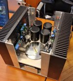
Finally, I finished Singing Bush 😊
At first I wanted to use a single 50 V / 1000VA transformer for both channels but I couldn't beat hum.
I switched to a Toroidy 2x 50V / 600VA and now I have dual - mono.
The amplifier is completely silent and with a sound as I expected, I really like it 😉
The radiators are 300 x400 x84 mm, after an hour they are at 50 degrees C.
Thanks to Zen Mod for this wonderful amplifier and for all his support!
Attachments


Well, the thing sounds very good.
I am getting more like 34.4 volts Vds. The other three are in the 36 volts range
And ZM's English is as plain as day. It is a plonker's brain that is the problem.
And yes, you are much like Tom Sawyer in getting us to build your amplifiers but you let us keep them for ourselves.
Do you see any value in lowering the value of R12 further to get more voltage across the SIT?
THANKS!!!!
replace that additional 17K with something lower (10K) and you'll be able to brake SIT little more, then Uds will rise
nice to have it same an all 4 channels
any news about Buzzer channel?
nice to have it same an all 4 channels
any news about Buzzer channel?
This last drama episode was the result of my installing the ZM CAP BANK in amp #2 along with updating the wiring arrangement to what had evolved with amps 3 and 4 and then my problem with the solder blob took me off course and wasted lots of time.
This weekend I am going to re-wire the buzzer so it is like the other three - SIT board is turned so the V+ wire from SIT to MOSFET board is less than one inch long - for amp #1 it is much too long and I hope it is the cause of the buzz. Amp #2 was initially wired the same way but did not buzz but hope springs eternal they say ...
Amps 1 & 2 used the first pair of devices I got from pras which were "matched". Seeing that no change had to be made to the bias circuit with amp #1 does show how unpredictable these devices can be.
And thanks to MASTER TINKERER ZM it don' matta.
I think it is funny that I used a TEXAS COMPONENTS Z foil as my parallel resistor. I am sure ZM is shaking his head but it was all I had.
I have learned my exotic resistor lesson and used the ones ZM sent for the SINGING BUSH. Well, except for using carbon composition for the gate stoppers on the vfets - but those do not cost twenty five dollars!
So even though over my fancy resistor fantasy I have them laying about and might as well use them. I have a 10K, too. what is nice about them is they can lay flay and I mounted the parallel resistor on the back of the pcb - plenty of room and nothing interferes with it laying flat against the board.
10K did not make any difference.
One unusual thing - I had installed a 600 VA 59 volts power transformer all wired in series.
I get the same B+ but this one run much warmer than the 300 VA one did before and the one in the other channel.
In every case, with this amplifier, the trimpot on the MOSFET board is turned all the way clockwise which I figure means close to 10k - do I install a larger value resistor at R1?
Is this to be expected? Is this SIT really current hungry?
Any ideas and suggestions?
just measure actual Ugs of that SIT and write here
SIT is not current hungry, it just needs more negative voltage a gate to be set where you need it
SIT is not current hungry, it just needs more negative voltage a gate to be set where you need it
- Home
- Amplifiers
- Pass Labs
- The Singing Bush Tips 'n' Tricks