So I would experiment with the orientation of the regulator to see if the 50Hz nulls a bit.
Tried this already back then, but to no avail. I'd probably have to do something with the PC itself, but since it is not solely for measuring purposes I didn't do this yet. I still hope to get better results though when my house is finished and I have my own room for tinkering 😎.
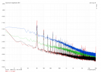
Here're some more measurements:
Black = Positive rail of Dual Salas CCCCS equipped with BF256B and no load
Red = Same, but with my ulti-preamp connected as load (~68mA per rail)
Green = CCCCS equipped with 2SK117GR and no load
Blue = Ground referenced CCS equipped with 2SK117GR and no load
Since I only found two of the 2SK117, I've used them to supply the zener current, while the other CCSes remained BF256B's.
And that's about it. Low frequency noise is about 10dB higher than with Jack's measurements, but his regulator was probably set for a different voltage. Overall performance is distinctly better than any of the LM317 circuits I've tested so far. A round of applause 😀

Attachments
Zener does better with more mA bias. Are the BFs running higher mA through?
Jack's had resistor instead of a Zener. Was @ 25V I think. Its adjustable.
Try LEDS string as Vref too.
Much better than your LM and TL experiments on first try, so it worked alright. Congrats.
Jack's had resistor instead of a Zener. Was @ 25V I think. Its adjustable.
Try LEDS string as Vref too.
Much better than your LM and TL experiments on first try, so it worked alright. Congrats.
Zener does better with more mA bias.
Are the BFs running higher mA through?
They do, actually. It's roughly 5mA vs. 10mA.
Jack's had resistor instead of a Zener.
Didn't put in a socket for the zener, but if I replaced the FETs with a jumper that'd be 15V zener plus 1k at ~30V, for roughly 16mA (and almost 300mW) zener current...
Try LEDS string as Vref too.
How about white LEDs? Wouldn't need as many as greens then 😉
See recent posts in the Blowtorch thread for some LED noise and tempco measurements and remarks. Blues (same chips as whites which have a phosphor over) are reputedly noisier and have a larger temp coefficient. They do tend to be "incandescent-blind" for photocurrents, which most of the time is a red herring anyway.How about white LEDs? Wouldn't need as many as greens then 😉
They do, actually. It's roughly 5mA vs. 10mA.
Didn't put in a socket for the zener, but if I replaced the FETs with a jumper that'd be 15V zener plus 1k at ~30V, for roughly 16mA (and almost 300mW) zener current...
I think that the noise steps are due to 10mA 5mA and then less when with VBE=VDS
Don't know about more current than 10mA maybe already enough. You could check. You could just parallel two FETS, couldn't you?
Can use small daughter board (perfboard about stamp size), stuff 3mm reds in series and with two pins go to the now Zener pads.
Also with 2K trimmer instead of Zener you could check noise shape and level to know if you got more potential, especially 1/F.
I have read a very few noise test results for LEDs.
It seems that they get quieter as the Vf goes lower.
So much so that two series connected REDs are quieter than a single Blue.
That would indicate that without testing that IR should be quieter than RED
and that quieter than Yellow/Green/Orange. Leaving White and Blue as the noisiest.
Based on this I have used 7 RED & Green LEDs to bias the BJT cascode of a jFET LTP.
They would be nice refs if it weren't for the temperature coefficient and the dynamic impedance. For biasing a current source, the match of the tempco to that of Vbe is very handy. However the 900mV to 1V delta V means the emitter resistor will have fairly large current noise for many useful currents.
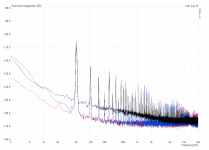
Some testing:
Black: Dual Salas CCCCS with BF256B and 15V zener || 1000uF for reference
Blue: Zener exchanged for 2k2 pot, set for 16V output voltage
Red: Zener exchanged for 7 red LEDs in series
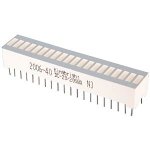
Red LEDs are clearly better than zeners here and look pretty neat when they're packed up as a bargraph 😎. I used one with 20 LEDs, which is enough for both rails 😀
Black: Dual Salas CCCCS with BF256B and 15V zener || 1000uF for reference
Blue: Zener exchanged for 2k2 pot, set for 16V output voltage
Red: Zener exchanged for 7 red LEDs in series
Red LEDs are clearly better than zeners here and look pretty neat when they're packed up as a bargraph 😎. I used one with 20 LEDs, which is enough for both rails 😀
Attachments
You folks may be following it, but there has been a recent and vigorous exchange in the Blowtorch Preamp thread about LED noise and possible photosensitive effects. And discussions include aging effects. Today someone posted this paper about LED degradation and the correlation or lack of correlation of electrical noise with noise and flux reduction in the light output.
Good stuff.
Good stuff.
Attachments
Some testing:
Black: Dual Salas CCCCS with BF256B and 15V zener || 1000uF for reference
Blue: Zener exchanged for 2k2 pot, set for 16V output voltage
Red: Zener exchanged for 7 red LEDs in series
Red LEDs are clearly better than zeners here and look pretty neat when they're packed up as a bargraph 😎. I used one with 20 LEDs, which is enough for both rails 😀
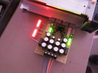
If we ignore the harmonic spray in your test rig, the noise floor is much better by now and seems like following older independent measurements. So your prototype works as it should. Lets find out if you can also hear any better music with it now in your specific line preamp vs your 317-337 experiments. Is it a low, medium, or high PSRR preamp? Don't forget to check on the oscilloscope that the rails will be oscillation free when the PSU is hooked on the preamp before any listening. Use shortest proximity and thickest wires possible. The long stored electrolytics usually come up fully in 48 hours of operation also, so don't expect 100% tone on first track. Hey, where is a picture of your prototype with the bargraph LEDS alight? That one should be a cool looking V1.0 build variation.
So those must be ~2.1V forward drop LEDs in the bargraph packaging.Some testing:
Black: Dual Salas CCCCS with BF256B and 15V zener || 1000uF for reference
Blue: Zener exchanged for 2k2 pot, set for 16V output voltage
Red: Zener exchanged for 7 red LEDs in series
Red LEDs are clearly better than zeners here and look pretty neat when they're packed up as a bargraph 😎. I used one with 20 LEDs, which is enough for both rails 😀
You folks may be following it, but there has been a recent and vigorous exchange in the Blowtorch Preamp thread about LED noise and possible photosensitive effects. And discussions include aging effects. Today someone posted this paper about LED degradation and the correlation or lack of correlation of electrical noise with noise and flux reduction in the light output.
Good stuff.
Lasse maybe can remember to re-measure his LED REF V1.0 after 2400h of powered on time and we will see if 1/F followed the paper, right?
Or contribute another paper on aging effects in his particular string 🙂Lasse maybe can remember to re-measure his LED REF V1.0 after 2400h of powered on time and we will see if 1/F followed the paper, right?
If we ignore the harmonic spray in your test rig (...)
Yup, ignore that... 😱
Lets find out if you can also hear any better music with it now in your specific line preamp vs your 317-337 experiments.
That will have to wait until the preamp is actually finished. Not sure if I'll try it with anything 317 then, though.
Is it a low, medium, or high PSRR preamp?
Not sure, I'm not that into PSRR just yet. Can you tell from the schematic? Ulti-Preamp preamp.org
Hey, where is a picture of your prototype with the bargraph LEDS alight? That one should be a cool looking V1.0 build variation.
Here it is. Working on a new layout for bargraph use. Adjacent jumpers or DIP switches to short out the not needed LEDs would make the output adjustable in ~2V steps.....
So those must be ~2.1V forward drop LEDs in the bargraph packaging.
No, it's actually more like 1.9V. 7 LEDs yield only 14V output, so Vref must be 1VBE lower. Changed it to 8 LEDs so I'm back at 16V now. Will have to re-test the noise 🙁.
Lasse maybe can remember to re-measure his LED REF V1.0 after 2400h of powered on time and we will see if 1/F followed the paper, right?
Wilco, Sir! 😀
Now I need to fit a power on time counter into the preamp... 🙄
Attachments
Not sure, I'm not that into PSRR just yet. Can you tell from the schematic?
Well, there are tail current sources for the symmetric differential input stages with their LED refs current held steady with a JFET, there is an RC 10R-100uF cell on the rail, there should be some PSRR. How much maybe LT Spice can tell if you will use AC sources for supplies and set them for 16V DC offset, some AC ripple too. Then ask it to check the preamp's output for how much ripple breaks through. And you could make a division.
- Status
- Not open for further replies.
- Home
- Amplifiers
- Power Supplies
- The simplistic Salas low voltage shunt regulator