EDIT posted before I saw the previous post
I like to look at a circuit in terms of the primary input(s) and output(s). This will allow the determination of the signal gain(s).
Then insert a noise generator somewhere and see what you get at the output.
A simple example: an inverting op amp with unity negative signal gain. Equal input and feedback resistor values, input from a low-impedance source applied to the input resistor. Now stick a generator in series with the otherwise-grounded noninverting input, and presume that the original input is effectively grounded.
What's the signal at the output? Clearly, from the standpoint of the noise signal, the circuit now looks like a noninverting amplifier with a positive gain of two. So for equivalent input noise of the amplifier, the circuit has a noise gain of two, and a signal gain of (minus) one.
@ Chris
I think they made a distinction because there is stability involved. So +1 can make a difference.
I think they made a distinction because there is stability involved. So +1 can make a difference.
Move on to consider the thermal noise from the resistors. In the example, insert the noise generator in series with the input resistor. Clearly, as this is indistinguishable from a normal signal, the noise gain has a magnitude of unity. The noise current in the feedback resistor will be the same as the input resistor, and since uncorrelated, the two will add root-sum-of-squares and flow in the feedback resistor. So the net output noise will be root 2 times each resistor's noise.
Hi Salas,
For checking out the stability of an amplifier circuit, they do use the noise gain and not the signal gain. The +1 can make a difference in some applications.
Hi Brad,
That's better than my attempt at explaining this.
-Chris
For checking out the stability of an amplifier circuit, they do use the noise gain and not the signal gain. The +1 can make a difference in some applications.
Hi Brad,
That's better than my attempt at explaining this.
-Chris
One can get a long way by using simple simulations and deterministic generators. Then just remember to combine the results as square-root-of-sum-of squares, when the noise generators are uncorrelated. Along with the formulae for shot noise and thermal noise, you can get pretty close to meaningful predictions, but certainly get close to insights.
A question may come up. Does it have any practical spec meaning beyond a factor in open loop analysis design? I will try a guess. It affects the total noise of an amp you would measure at its output with a shorted input. Right?
Most noise gain examples I've seen pertain to closed-loop configurations, although for accuracy one does need to know the open-loop phase/gain, especially if you're pushing the stability margins.
In another thread I speculated about pushing Cordell's notion of realizing the 75us RIAA tau, which he does by heavy resistive loading of MM/MI cartridges, into the realm of typical low-inductance and low-resistance MC's, by synthesizing a negative resistance. Simulations indicated that the idea would work, but the requirements on the linearity of the circuitry to realize the negative impedance were incredibly stringent if one was to have acceptable distortion. I suspect the same was true of the noise gain, but I didn't take things any further. For one thing, the requirement of knowing the inductance of a given cartridge seems to rule out the approach for anything other than DIY.
As far as a shorted input, that's of course how one must measure voltage noise. It's what about everybody does for characterizing phono preamps, but for MM preamps it's quite wrong, as it neglects current noise from the termination and the preamp input device(s). This was noted many years ago in a National Semi article about estimating phono preamp noise. It was in their Audio Handbook, and it was amusing, as a bit in the main text pushing one of their chips was effectively in conflict with the detailed article relegated to an Appendix.
Somewhere Atkinson has gotten it in his head that the most stringent test of a preamp or amplifier is to short its input and measure at maximum gain. If the input source is very low impedance this may well be of interest, but even for power amps the source may have some appreciable impedance. So the current (or "parallel") noise could be significant. Now if the input stage is a resistor to a summing node, then grounding the input will have the highest noise gain for equivalent input voltage noise. This may be where JA got the notion. But I don't think hardly anyone does that, as to get low thermal noise from the resistors you need low values which are then tougher to drive. It does minimize common-mode distortion though.
For cartridges with of order half a henry of inductance, the parallel noise of the preamp can be quite significant, although concentrated at frequencies that a lot of people don't hear anymore. Failure to note this leads people to specify some of the latest ultra-low voltage noise and low-distortion ICs for MM preamps. It's even shown as a circuit example on the TI spec sheets. But the high current noise makes them a less-good choice, other than for specsmanship. There are a few JFET amps still extant with decent voltage noise and small current noise, and one can synthesize a lower-than-thermal noise termination for the ubiquitous 47k without a lot of fuss. There's not much point to doing it for low inductance/resistance MCs.
variation on a theme...
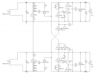
Here's an idea that just struck me while doing the dishes. I was thinking about cascading two JFET current sources, where the first source (with 2x current) keeps a constant voltage over a resistor, which then is the reference for the second CCS. In the attached schematic the first source is comprised of J7 and J8 for the positive half. They're in parallel to double their current, which is then divided between R1 and the second current source J2. This makes the voltage over J2 a lot more immune against variations in output voltage, while having about the same temperature coefficient. Would this make any sense in this case? What's the effect on output noise? At least it would add another 'C' in the name, so now it's "Cross Coupled Cascaded Constant Current Source" 😀
Here's an idea that just struck me while doing the dishes. I was thinking about cascading two JFET current sources, where the first source (with 2x current) keeps a constant voltage over a resistor, which then is the reference for the second CCS. In the attached schematic the first source is comprised of J7 and J8 for the positive half. They're in parallel to double their current, which is then divided between R1 and the second current source J2. This makes the voltage over J2 a lot more immune against variations in output voltage, while having about the same temperature coefficient. Would this make any sense in this case? What's the effect on output noise? At least it would add another 'C' in the name, so now it's "Cross Coupled Cascaded Constant Current Source" 😀
Attachments
Last edited:
Many are the ways. I don't think it will hurt noise, but I suspect the noise will be dominated by zener noise in any case. Depends a lot on the particular zener samples.Here's an idea that just struck me while doing the dishes. I was thinking about cascading two JFET current sources, where the first source (with 2x current) keeps a constant voltage over a resistor, which then is the reference for the second CCS. In the attached schematic the first source is comprised of J7 and J8 for the positive half. They're in parallel to double their current, which is then divided between R1 and the second current source J2. This makes the voltage over J2 a lot more immune against variations in output voltage, while having about the same temperature coefficient. Would this make any sense in this case? What's the effect on output noise? At least it would add another 'C' in the name, so now it's "Cross Coupled Cascaded Constant Current Source" 😀
I might have a comparable 15V zener that I could bypass with 10uF and see what it looks like.
For really high impedance I recommend a cascoded structure, which requires a significantly higher pinchoff voltage and Idss JFET as the cascode device. But since you are just supplying current to a zener, which is rather low impedance, the I source impedance is a fairly small effect.
one zener's noise
We like zeners for low impedance, but reducing noise by direct bypassing requires large C. If instead the filtering is done with an R-C lowpass, it's much easier, and not much is lost used as a reference as long as current noise from the error amp has a small effect.
I found a 1N5245B to test, and it is pretty noisy. More current helps, and at 15mA, which was as high as I wanted to consider for a 500mW part, the 10uF bypassed noise in a 22Hz to 22kHz bandwidth was 29uV rms. Bypassing with 2200uF reduced this to 5.5uV. I did not measure the zener impedance but I'm guessing it's around 10 ohms, so 2200uF represents a time constant of 22ms.Many are the ways. I don't think it will hurt noise, but I suspect the noise will be dominated by zener noise in any case. Depends a lot on the particular zener samples.
I might have a comparable 15V zener that I could bypass with 10uF and see what it looks like.
We like zeners for low impedance, but reducing noise by direct bypassing requires large C. If instead the filtering is done with an R-C lowpass, it's much easier, and not much is lost used as a reference as long as current noise from the error amp has a small effect.
meanwhile in other reference developments
I went ahead and breadboarded a temperature-compensated JFET current source, using the obsolete 2SK381 (probably close to a 2N5459). I made four sets of sources using 4 381s and a 2SK246GR for each of the four. The source resistor for each quad of 381s was 1.33k. This ensemble wound up generating 6.23mA, and the closest resistor I had of suitable pedigree (RN65) to use the current to generate a voltage was 2.61k. Temp stability could be further tweaked by adjusting one or more of the source resistors.
I wanted the voltage to be at a reasonably low impedance to make the effects of error amp base current noise small. This is a nontrivial noise source if one is running at healthy collector currents to make the equivalent noise voltage small.
I bypassed the 2.61k with 10uF. The pickup loop of the cap leads was enough to get significant hum, so the Ap was highpassed at 400Hz. Noise to 22kHz was strongly dominated by the Ap. I made a gain of times |30| preamp with a 2SK364BL part (same die as 2SK170BL) and a 1k drain resistor run from two 9V batteries, and a.c. coupled with a series 1uF and 1.2M to preamp common.
The noise is still not readily distinguishable from the <1nV/sq rt Hz makeshift preamp for a shorted input. Calculations based on thermal noise in the I source resistors predict about 61nV rms. This should be roughly at parity with other noise sources in the anticipated shunt regulator, using the very low rbb' bipolars, except at very low frequencies.
Hi Brad,
Were those 10 uF capacitors film, tantalum or electrolytic?
Sounds like I have to make a very low noise signal amplifier to play in that neck of the woods. But with phono amplifier work in the future it will be required. I'm hoping some of the gear I have on the bench might do, because an AP is not in the cards.
-Chris
10uF films are on order, along with some On Semi TL431 for that other investigation. The cap I used was a 350V electrolytic, a 105C Panasonic of fairly recent vintage.Hi Brad,
Were those 10 uF capacitors film, tantalum or electrolytic?
Sounds like I have to make a very low noise signal amplifier to play in that neck of the woods. But with phono amplifier work in the future it will be required. I'm hoping some of the gear I have on the bench might do, because an AP is not in the cards.
-Chris
Hi Brad,
Okay, that would still be a good capacitor. I don't know if the film type would have less noise or not.
-Chris
Okay, that would still be a good capacitor. I don't know if the film type would have less noise or not.
-Chris
It should be a small effect. But, I did notice increased noise with a larger electrolytic, so films are indicated if they are not too bulky.Hi Brad,
Okay, that would still be a good capacitor. I don't know if the film type would have less noise or not.
-Chris
Received the prototype boards today. Was happy that I got two while having ordered just one, but then noticed that I messed up the gerbers and the bottom layer is on the top side 😱. No problem if the board was plated through, buuuut - no. It's not. 
Now this is going to be one hell of a f...king ugly prototype

Now this is going to be one hell of a f...king ugly prototype
Prototypes need be ugly to work right. Worked for Bob Pease so it should work for us dummies too. No worries.🙂

I see in the sames series there is a 100uF 63V film. But they are expensive.It should be a small effect. But, I did notice increased noise with a larger electrolytic, so films are indicated if they are not too bulky.
Hi Brad,
Yes, they can get pretty dear. They aren't even audiophile approved! 🙂
I top out around 10 uF. Any higher and I'm looking for ways to eliminate or reduce the capacitance without losing too much performance.
-Chris
Yes, they can get pretty dear. They aren't even audiophile approved! 🙂
I top out around 10 uF. Any higher and I'm looking for ways to eliminate or reduce the capacitance without losing too much performance.
-Chris
Prototypes need be ugly to work right. (...) No worries.🙂
Thanks 😱. It's actually not as bad as I imagined in the first place. By rotating some of the transistors I was able to populate the board in a normal way and didn't have to solder the caps from the top side
 .
.The good thing: It actually works like it's supposed to. When I set the jumper to the standard (ground referenced) setting it doesn't work with BF256B, kinda like the sim suggested. I'll try some SK117 (which should exist in the workshop) and see what a difference it makes.
A photo and some scope plots are soon to follow, but the proper measurement might take me some more time, since I just received my building approval these days.
- Status
- Not open for further replies.
- Home
- Amplifiers
- Power Supplies
- The simplistic Salas low voltage shunt regulator