You folks may be following it, but there has been a recent and vigorous exchange in the Blowtorch Preamp thread about LED noise and possible photosensitive effects. And discussions include aging effects. Today someone posted this paper ab
the clear diodes like 1N4148, 1N914 can be modulated by fluorescent light.
Did a final measurement of the positive rail with 8 red LEDs for 16V output.
Red: Noise floor with DUT hooked up but unpowered, 40dB preamp.
Black: Same thing, but powered up.
This time I've used 128k FFT resolution for maximum performance. Mains noise didn't get much better, although I've used double shielded coax this time, right from the psu output. -170dBV at 50Hz now actually looks better than Jack's measurements ! And it's only about 6dB more than the noise floor, which looks pretty good I'd say. Now I just have to re-build my LNA with a Dual Salas psu, which should reduce the noise floor even further...
Red: Noise floor with DUT hooked up but unpowered, 40dB preamp.
Black: Same thing, but powered up.
This time I've used 128k FFT resolution for maximum performance. Mains noise didn't get much better, although I've used double shielded coax this time, right from the psu output. -170dBV at 50Hz now actually looks better than Jack's measurements
! And it's only about 6dB more than the noise floor, which looks pretty good I'd say. Now I just have to re-build my LNA with a Dual Salas psu, which should reduce the noise floor even further...Attachments

And incandescents too, although the double-mains-frequency modulation is much attenuated by the filament thermal time constants.the clear diodes like 1N4148, 1N914 can be modulated by fluorescent light.
I mentioned in the other thread how the effect was significant enough that I had to migrate to opaque packages for some input protection diodes. Rather than SM packages I used diode-connected JFETs.
Did a final measurement of the positive rail with 8 red LEDs for 16V output.
Red: Noise floor with DUT hooked up but unpowered, 40dB preamp.
Black: Same thing, but powered up.
This time I've used 128k FFT resolution for maximum performance. Mains noise didn't get much better, although I've used double shielded coax this time, right from the psu output. -170dBV at 50Hz now actually looks better than Jack's measurements
Jack's had adjustable Norton Vref (resistive) with 220uF across. Which can match LEDS only down to little before subsonic. You got an advantage under 20-40Hz anyway, you also got a big 1000uF across meant to tame your Zener originally. At least you stay in advantage while your LEDS are still fresh says that evil paper.😀
We usually avoid so much capacitance with K117GR under Vbe weak mA not to be taking too long to charge up since the output noise is already very low.
So it makes sense yours should be somewhat better in-band with even better subsonic 1/F portion. The best thing is it computes with other measurements.
Good we are not just theorizing about your build here, its yet another low noise build indeed. Congrats.🙂
At least you stay in advantage while your LEDS are still fresh says that evil paper.😀
Yeah, the evil overlord of noise papers... I think performance will still be fine, even after 3k hours have passed. Otherwise I'll have to install a socket for the bargraph for easy servicing after a couple of years. Or better yet once every year 🙄. Oh, and don't forget the self adhesive copper tape to cover up the LEDs, but watch out for shorts!
Good we are not just theorizing about your build here, its yet another low noise build indeed. Congrats.🙂
Thanks! Add to that the advantages of being able to use pretty much any JFET with high enough voltage rating and yielding around 10mA, and the fact that one rail drops to ~4V should the other one fail. It's intrinsically fail-safe 😎.
They may have something to do with the opposite supply trying to reverse bias the circuit during startup/shutdown/failuremode.
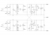
D2 and D3
They are there to prevent excessive reverse biasing of the error amp transistors from output transients in power-down or output shorts, via C5 and C8. Such is a beta degradation mechanism is cumulative.
How do D2 and D3 work ?
They are there to prevent excessive reverse biasing of the error amp transistors from output transients in power-down or output shorts, via C5 and C8. Such is a beta degradation mechanism is cumulative.
The cross referencing to the rails is neat for using more JFET types, but applicable only to symmetric supplies. Are R2 & R11 designated by 10 times different values due to a typo?
Are R2 & R11 designated by 10 times different values due to a typo?
Whoops! That's right, my bad. 😱
I used 1k each to split the load between FET and resistor. 100R works just fine, probably even if one side is 1k and the other 100R, but this puts some more stress on the FET. I like them as cool as possible 😎😀
Attachments
The cross referencing to the rails is neat for using more JFET types, but applicable only to symmetric supplies.
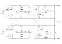
At least according to simulation that statement is not quite true. Since the opposite rail is only used to add some more voltage to the VBE of the bipolar, it may be of any value that the CCS FET can handle. Of course you'd have to adjust the series resistor (1k in my case) so that there's still enough voltage left for the FET. I just tried it with +8V and -14V in the sim and it works just fine. Had to halve the accopanying 1k so that there's about 5V over the FET again. Using like 100R in the first place would leave enough headroom for a multitude of output values, but one has to watch the max. dissipation of the FET with higher output voltages then. Otherwise it's pretty easy to (roughly) adjust the resistor according to the desired output voltage.
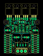
This is what a small, 5x5cm dual layer board for cheap chinese boardhouse fabrication might look like. It's meant for smaller currents in the range of 50mA, having opamp circuits like low noise measuring preams or headamps in mind. In this configuration with 2x 10-LED bargraphs (a 20-LED graph is already 5cm long and hardly fits on the board!) I used 3 LEDs each for the main CCS reference and the remaining 7 for the voltage reference, so we're at +-14V with red bargraphs. Some LEDs may be shorted for 12V, 10V or even lower output voltages.
Attachments
At least according to simulation that statement is not quite true. Since the opposite rail is only used to add some more voltage to the VBE of the bipolar, it may be of any value that the CCS FET can handle. Of course you'd have to adjust the series resistor (1k in my case) so that there's still enough voltage left for the FET. I just tried it with +8V and -14V in the sim and it works just fine. Had to halve the accopanying 1k so that there's about 5V over the FET again. Using like 100R in the first place would leave enough headroom for a multitude of output values, but one has to watch the max. dissipation of the FET with higher output voltages then. Otherwise it's pretty easy to (roughly) adjust the resistor according to the desired output voltage.
I should have used the word "bipolar" but as they are usually set to equal and opposite I used "symmetric" habitually.
This is what a small, 5x5cm dual layer board for cheap chinese boardhouse fabrication might look like. It's meant for smaller currents in the range of 50mA, having opamp circuits like low noise measuring preams or headamps in mind. In this configuration with 2x 10-LED bargraphs (a 20-LED graph is already 5cm long and hardly fits on the board!) I used 3 LEDs each for the main CCS reference and the remaining 7 for the voltage reference, so we're at +-14V with red bargraphs. Some LEDs may be shorted for 12V, 10V or even lower output voltages.
It will look very nice. Do you have the part number of the LEDS package so we at least know one that's verified low noise?
Thanks. Known brand. Do they measure fairly consistent Vf cell by cell in this type? Because people tend to meticulously match the discrete Vref LEDS in their DCB1s for instance. I mean I would like to make their life easier if a future re-spin is ever demanded due to possible key parts unavailability at a point since that project seems like it loves living forever, but if not having almost spot-on symmetrical chance with the bar-graphs it would take small value vernier trimmers in series to each column, else the fans will be unhappy. But for not matching and looking for orientation and burning the odd 3mm LED with a bit too much time with the iron, I think they would be happy with the verniers.
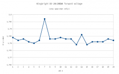
I only have this one bargraph here, so the following measurements are by no means representative.
Measured with a DCA75 Pro at 5.00mA each:
Measured with a DCA75 Pro at 5.00mA each:
Code:
LED Vf@5mA
----------
 1: 1.784V
 2: 1.782V
 3: 1.783V
 4: 1.781V
 5: 1.780V
 6: 1.782V
 7: 1.797V !
 8: 1.783V
 9: 1.783V
10: 1.784V
11: 1.783V
12: 1.783V
13: 1.779V
14: 1.786V
15: 1.779V
16: 1.781V
17: 1.781V
18: 1.781V
19: 1.783V
20: 1.782V
Attachments
Last edited:
- Status
- Not open for further replies.
- Home
- Amplifiers
- Power Supplies
- The simplistic Salas low voltage shunt regulator