Salas,
What's the max possible current and min. suggested current with both regs?
Its a matter of the CCS limit you impose (MOSFET type & its sinking). For the typical SSLV1.1 and Reflektor using IRF9610 20mA-1000mA I would say. For a DCB1 regulator section and big sinks, up to few Ampere.
Thanks, Salas. For a 12V amplifier that has up to 9A of output current (peak), 22W power (w/ 14.4Vcc) and 250ma max. Iccq (Vin=0), would the DCB be enough?
It would be much inefficient. Huge thermal loss to shunt reg's sinks. You would want a Class A amp with high Iq and low Iq to peak current ratio so it shares the reg's idle better.
A power capacitance multiplier should be a fitting solution. Like this http://www.diyaudio.com/forums/power-supplies/51817-improving-capacitance-multiplier.html
There have been some variations also http://www.diyaudio.com/forums/powe...lified-mrevil-pmi-capacitance-multiplier.html
There have been some variations also http://www.diyaudio.com/forums/powe...lified-mrevil-pmi-capacitance-multiplier.html
I just thought of this. Do I need to use 1 BiB+ & 1BiB- for each channel or can one set of boards feed both channels? (Using to power a DCB1 XO and due to size considerations, each channel will be own its own board.) Assuming I can use one board for both channels, what does that do to the remote sensing? Do I just use 4 wires going to each channel and then there are two wires in each connector on the BiB board?
You should bridge the channels power receiving and power ground points between them with heavy gauge copper wire, and attach the relevant force and sense wires at the bridges midpoints.
Easy.You should bridge the channels power receiving and power ground points between them with heavy gauge copper wire, and attach the relevant force and sense wires at the bridges midpoints.
Thanks!
Salas,
Sorry if I abuse of your time. If the application draws around 10mA only (like a CS8412 receiver) can we still use the Reflektor? Any extra modification needed?
Sorry if I abuse of your time. If the application draws around 10mA only (like a CS8412 receiver) can we still use the Reflektor? Any extra modification needed?
You can set it down to 3.3V but keep 200mA-300mA so it runs well in itself no matter the low load draw. With the sinks it got its very safe.
You can also set about 8.3V output if using an LM329 instead of LEDS (LM329 cathode facing the opposite way than if it was an LED).
2.5V out is too little for the voltage margins in the mirror circuit, out of spec.
You can also set about 8.3V output if using an LM329 instead of LEDS (LM329 cathode facing the opposite way than if it was an LED).
2.5V out is too little for the voltage margins in the mirror circuit, out of spec.
just to make sure: for 8.3V I use one LM329 on LED1 position (with cathode on the round pad) and jumpers on LED2 and on Rx/j/d?
Why the voltage reference small value bypass capacitor was ditched from the later Reflektor schematic?
After some subjective evaluations from early builders they were supposed unnecessary, not that they create a technical problem with stability.
After some subjective evaluations from early builders they were supposed unnecessary, not that they create a technical problem with stability.
Assuming there is a small value resistor in series?
Even without it was stable. I put that small resistor in order to damp any possible ringing between the large and small cap due to parasitic inductance in the bypass circuit.
Hello Salas
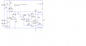
I am revisiting the V12R shunt because I do know it's potential and would like to push it a little further.
The initial schematic is below and I would like to drop C2 (47uF EL).
I know the BiB and the folded shunt can both work perfectly without that output EL.
The différences I see are related with the resistor value in the output zobel that in the BiB is 1.2ohm and in the V12R is 0.22 ohm.
Can I take the V12R schematic, drop the output EL and raise the zobel resistor to 1.2ohm and expect it to work without oscilations ?
Attachments
- Status
- Not open for further replies.
- Home
- Amplifiers
- Power Supplies
- The simplistic Salas low voltage shunt regulator