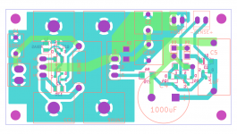
The loop areas aren't tight and long distance bypassing isn't productive, but it should work electrically. As for correct routing I am not sure, can't be following it in detail with a fast look. Just check everything twice.
P.S. Where are the Leds for CCS? Using one Vbe transitor current control voltage?
Thanks for the input. Do you mean that the trace between the two MOSFETs is too long? Yes, I've borrowed the CCS section from the Reflektor, as it is more compact.
Last edited:
Sense and force pairs could be running closer in general having narrower loop area. Q1 under RLIMIT is not a thermally good place also.
Sense and force pairs could be running closer in general having narrower loop area. Q1 under RLIMIT is not a thermally good place also.
OK, would this be considered an improvement?
Attachments
Looks better now, yes. Are you using a Zener reference?
No, D1 is a 1N4148, D2 and D3 are WP2773 LEDs.
Better use green ones because the current won't be much in the ref.
That's the plan. Can't the current be upped by selecting a Q303 with higher Idss though?
Up to a point that it must not have Vgs(off)>0.6V. Loses much Idss in circuit's VDS=Vbe. Can always replace the diode with a proper resistor if it will end up <>5V out.
Up to a point that it must not have Vgs(off)>0.6V. Loses much Idss in circuit's VDS=Vbe. Can always replace the diode with a proper resistor if it will end up <>5V out.
Got it. Thanks for the tips, Salas!
I am building a dual PSU for the Dam1021 R-2R DAC.
I have finished a positive supply of 12V with 300mA.
Just wonder whether I use the negative BiB board to build the -ve supply (unkown Vgs of IRF610) or use another piece of +ve supply (Vgs of IRF9610 is the same as the +ve one) and connect 2 to give +12--0---12.
Another question: since the Dam1021 DAC uses about 180mA in the +ve rail and only 60mA in the -ve. Should I build the -ve supply with 300mA (same as the +ve) or reduce it to ~150mA to reduce heat dissipation (the two halves of the transformer have different current load)?
As I run out of jfets, I use CRD E-202, E-352 and E-562 (2mA, 3.5mA and 5.6mA respectively) as current sources. I used E-352 as current source replacing Q103 and 1K for R103 and 2k for R105. The voltage output (7.8V) is far away from my calculated one (12V). Fortunately, I have some 6.2V zener sitting around and I replaced the jumper with the zener at position D101 and eventually obtained 12V. Why does the output voltage deviate so much from the calculated one? Is there any payoff for using CRD as current source in comparison with jfet?
Those current regulative diodes don't have same characteristics as the BOM JFETs in place. Check Vdrop on R103 to derive the actual current in the Ref to compensate for resistor value. Check datasheet if such current is still adequate for the CRD. Hope noise performance also is adequate at least. Those builds with different layout and/or parts are quasi bibs, not the exact reg.I am building a dual PSU for the Dam1021 R-2R DAC.
I have finished a positive supply of 12V with 300mA.
Just wonder whether I use the negative BiB board to build the -ve supply (unkown Vgs of IRF610) or use another piece of +ve supply (Vgs of IRF9610 is the same as the +ve one) and connect 2 to give +12--0---12.
Another question: since the Dam1021 DAC uses about 180mA in the +ve rail and only 60mA in the -ve. Should I build the -ve supply with 300mA (same as the +ve) or reduce it to ~150mA to reduce heat dissipation (the two halves of the transformer have different current load)?
As I run out of jfets, I use CRD E-202, E-352 and E-562 (2mA, 3.5mA and 5.6mA respectively) as current sources. I used E-352 as current source replacing Q103 and 1K for R103 and 2k for R105. The voltage output (7.8V) is far away from my calculated one (12V). Fortunately, I have some 6.2V zener sitting around and I replaced the jumper with the zener at position D101 and eventually obtained 12V. Why does the output voltage deviate so much from the calculated one? Is there any payoff for using CRD as current source in comparison with jfet?
Same CCS overhead above load gives same Zo to the sections, so target same extra current than absolute CCS current.
Using two positives on top of another like batteries with center point floating "zero" ref is a classic acceptable alternative if it mixes well with the rest of system grounding.
As I run out of jfets, I use CRD E-202, E-352 and E-562 (2mA, 3.5mA and 5.6mA respectively) as current sources. I used E-352 as current source replacing Q103 and 1K for R103 and 2k for R105. The voltage output (7.8V) is far away from my calculated one (12V). Fortunately, I have some 6.2V zener sitting around and I replaced the jumper with the zener at position D101 and eventually obtained 12V. Why does the output voltage deviate so much from the calculated one? Is there any payoff for using CRD as current source in comparison with jfet?
According to the data sheet, E-352 across 0.6V should sink (0.8 * Ip) * (0.6 / Vk) = 0.525mA, probably not the value you used in your calculations.
According to the data sheet, E-352 across 0.6V should sink (0.8 * Ip) * (0.6 / Vk) = 0.525mA, probably not the value you used in your calculations.
Vorozhtsov:
Thank you for your comment.
Now, I understand why I got a much lower output voltage.
Those current regulative diodes don't have same characteristics as the BOM JFETs in place. Check Vdrop on R103 to derive the actual current in the Ref to compensate for resistor value. Check datasheet if such current is still adequate for the CRD. Hope noise performance also is adequate at least. Those builds with different layout and/or parts are quasi bibs, not the exact reg.
Same CCS overhead above load gives same Zo to the sections, so target same extra current than absolute CCS current.
Using two positives on top of another like batteries with center point floating "zero" ref is a classic acceptable alternative if it mixes well with the rest of system grounding.
Salas,
Thank you for the comments.
I have struggled with finding the unobtainium from toshiba *_*
Anyway, I will connect the quasi BiB and see how it works.
Last edited:
Can you find 2SK880GR SMD for Q103 at least? Some through hole adapter should come handy. For other positions watch it, its 100mW device. Depends on voltage levels.
Optimum value for Q103?
I just measured the jFETs that came in my 'mini-kit' with the BiB boards from TeaBag. They range from 2.8mA-4.3mA with matches @ 2.9 & 3.3. My question is: what is the preferred value for Q103? I notice that the calculator has a default of 4 and that varying Idss of Q103 changes the calculated value for R103/105. Should I use the higher or lower Idss jFETs for Q103? Does it matter if V+ and V- boards have matching Q103 (assuming R103 is adjusted appropriately? What about the other locations? Is there a preferred way to distribute matched jFETs or high/low ones?
Just to be sure, my measuring setup is 9V battery ( (9.65V) > 10R >D of jFET , G+S > gnd. Measure V drop over 10R, divide by 9.9 (actual measure of R) = Idss. This is correct isn't it?
The manual says: "Q303 JFET will be weaker for IDSS in circuit from what you had measured with a 9V battery. A circa 4mA IDSS 9V testing JFET gives you around 3mA."
That is 25% less. So you can roughly predict the actual in circuit Iref of any Q103/203/Q303 K117GR JFET sample when knowing its IDSS under a 9V battery test. Enter that prediction to the calc. The difference with various Iref is how fast the available current will charge an electrolytic if using C101 and not the plastic cap C102 position. Nothing else or significant apart from calculating and using other resistive values between sections if Iref are much different. Every JFET sample is useful in SSLV1.1, only try group them per position between regs the nearer they come. Use the stronger ones in hand for Q102/202/302, the medium for Q103/203/303, the weaker for Q105/205/305.
Its correct the way you measure if your DMM is repeatable in few mV area, 100 Ohm creating more drop, maybe more helpful to it.
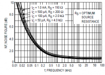
Salas, how critical is the noise figure of the transistors used in the Reflektor's current mirror? I'm tempted to try http://www.nxp.com/documents/data_sheet/PMP5201V_G_Y.pdf to avoid matching and thermal coupling (not to mention the smaller package), which looks a lot like BC856B, except for higher typical NF@1Khz (3.1 vs 2dB). Can't seem to find the noise data on modern 2N4403/MMBT4403, an old Motorola datasheet specifies ~2dB.
2N4403 are circa 50 Ohm Rbb' low noise transistors. Although not champions, certainly very good for cheap & common to get. A BC550 has triple the base spreading resistance. As for how critical in the reg, well, they are the main non filtered contributors. Nothing is left to chance in this apparently very simple Reflektor.
Attachments
- Status
- Not open for further replies.
- Home
- Amplifiers
- Power Supplies
- The simplistic Salas low voltage shunt regulator